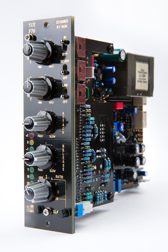
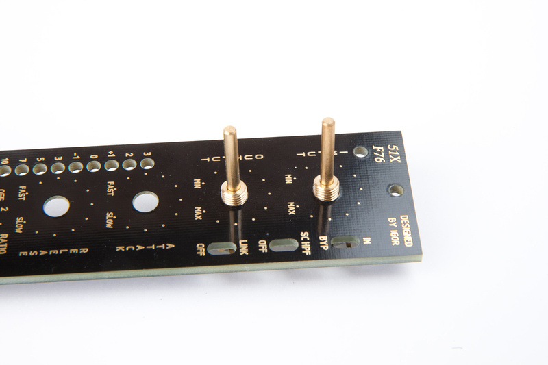
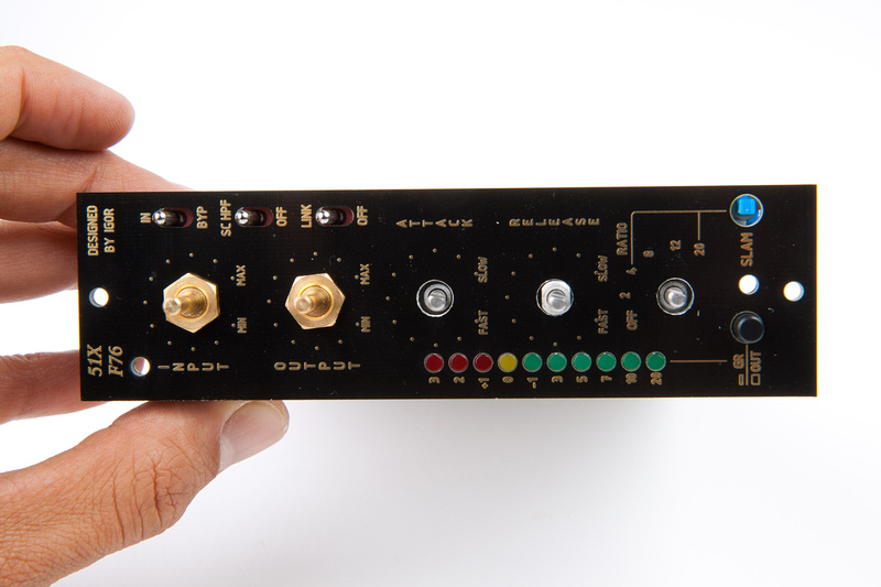
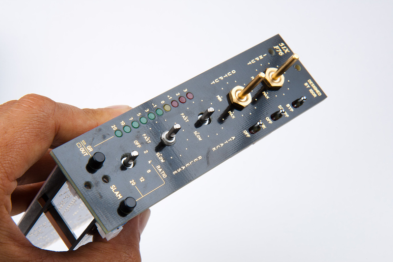
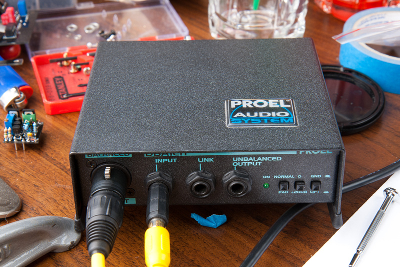
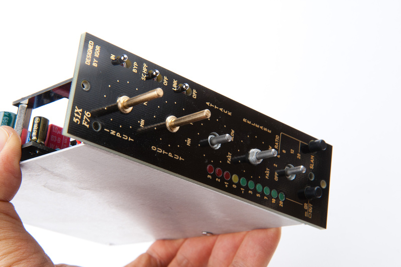
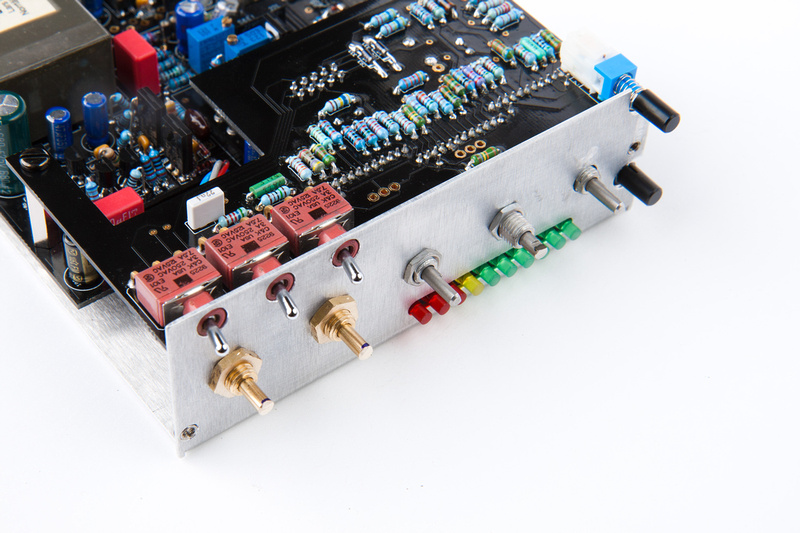
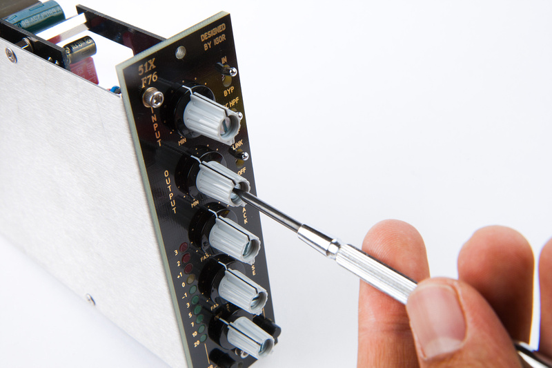
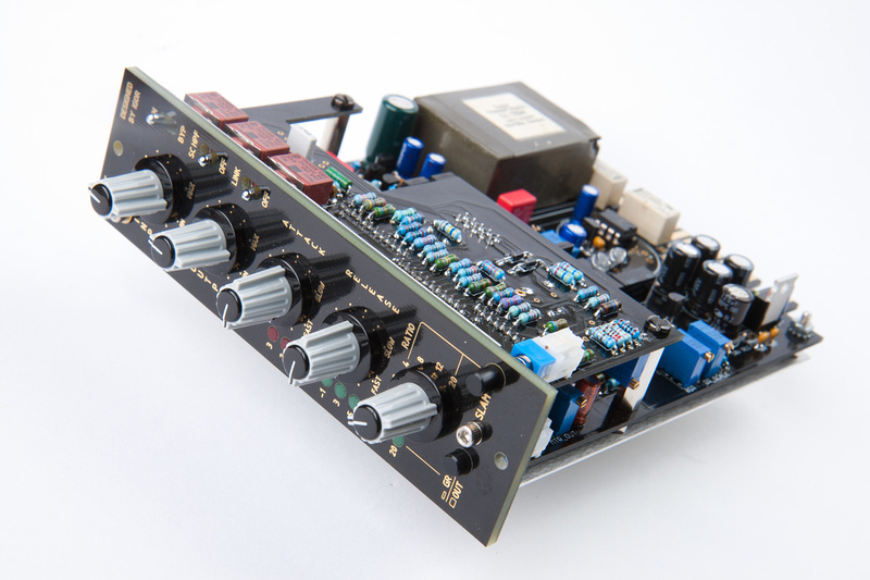
The I.J. Research F76 is a 51X format FET compressor designed around Universal Audio's revision F 1176 with a few very useful added features most notably, the addition of a 2:1 ratio, a side-chain high pass filter, and relay controlled true bypass. The kit also allows for a myriad of build options.
Igor Kapelevich based in Haifa, Israel can only be described as a prolific designer, and he is the mastermind behind the F76 compressor. Igor's primary business is building complete turn-key audio devices for various studios worldwide and his custom work is not cheap, but he is very active in the DIY community and makes his partial kits and PCB's available for purchase as a side business so that DIY people have an opportunity to build some fantastic sounding pieces of audio gear at very reasonable prices. For support and technical questions regarding this project, please refer to the official support thread. To purchase PCB's and font panel/hardware kits check out the IJ Research webstore. Complete kits may be available again from time to time depending on Igor's current stock of parts. In this post, I will try to show a complete build from start to finish.
As I began my DIY adventures, my first order of business was shoring up the studio's preamp options. At this point, we had some nice preamp options built so my attentions turned to finding a pair of nice tracking compressors. While we do run real tape and mix through a large format console, the majority of our work is now digital and there are some really nice plug-ins available for compression. It is a balancing act trying figure out which analog pieces are worth the cost and time to build. For a part-time small-budget operation like mine, we have to pick and choose our battles wisely.
I decided the 1176 is a solid, economical choice and there are many DIY options for building this circuit all of which end up costing about $500. First, there are multiple physical formats (single, dual, and in my case 51X format). There are also at least 6 different revisions of this circuit produced by Universal Audio. Hairball Audio stocks critical parts, PCB's and kits for quite of few of these revisions in the standard 2U rack-mount format. For my studio, space is a major concern and the idea of cramming a pair of 1176 type compressors into 2 500 series modules seemed ideal.
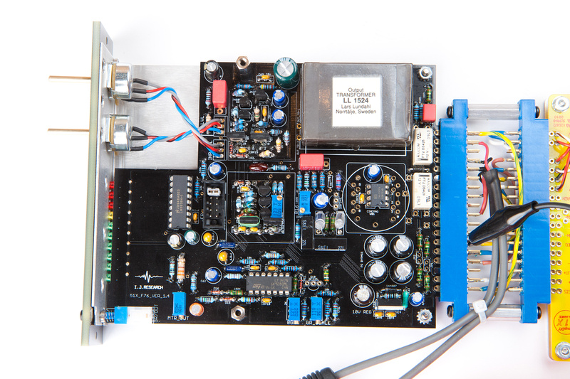
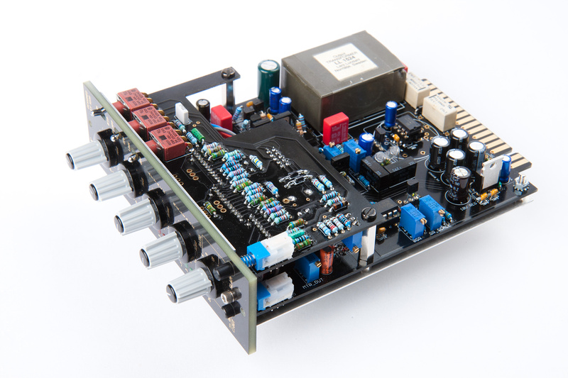
F76 is a pure 51X format module meaning it is designed to use the 51X spec +/- 24V power rails if the kit is built to its native configuration (using the original circuit). Igor has cleverly adapted the input and output amp sections of the circuit to standard 2520 footprint modules and the kit comes with sub-PCB options to build a variety of input and output amp options including the original circuit based on revision F. It should be noted that the original output transformer is too large to fit, but options for several functional transformers are provided. The original input transformer does fit and provisions are made on the PCB should you choose to use input iron.
The overall experience building on of the I.J. Research kits is significantly different than the previous kits I have attempted which have all been essentially "paint-by-numbers" sorts of operations. Certainly people who are more electronically literate than me are able to understand at deeper levels what is happening, but essentially, all you had to do in the previous projects was make sure all the parts end up stuck in the right location and everything would be fine. The F76 is a "big boy" kit and is not set up the same way. Igor likes to design his kits with options, options, and more options for the builder. F76 can be build with input pot and IC line receiver or input transformer and t-pad. There are various input and output transformer options that would fit. The attack/ratio/release sections can be built with pots or stepped resistor switches. There are several different sub-PCB options included for input and output amps including Igor's own cascode-topology input amp design, the original 1176 rev. F input and output sections, an IC based input and output amp design, and of course, because the pin format is 2520 compatible, a whole slew of commercially available input and output amp options are possible. The kit can even be configured to operate at the VPR standard +/- 16V and run API-type opamps with API-type input and output transformers. Depending on which build option is selected, many of the component values shift. Instead of providing step-by-step type guides for assembly, Igor seems to pride himself on generating very clear, educational schematics and brief, concise descriptions for each available option. Often, components are not set to a specific value, but instead, a range of values is recommended. Igor is not as much concerned with providing a concretely defined product that delivers a specific sound, but provides a canvas or platform on which endless options, mods, and tweaks can be performed to customize to the builder's needs and taste. Also, because kits are not the primary business emphasis of I.J. Research, there is a much longer lead time to getting answers and individual support for questions that come up. I get the sense that Igor values experimentation, cross-pollination of ideas, and a deep understanding and appreciation of analog circuit design and does not appreciate it when people do not do their homework and repeatedly ask questions that are already answered in his meticulous documentation and schematics. "Study the schematics" is a very common answer that Igor will give to questions asked by folks looking for easy handouts. That being said, although not as accessible as some of the other kit designers, Igor has always been extremely cordial, helpful, and of great humor when I have tracked him down about a specific question. He is prolific in his designing and strives to deliver designs of the highest sonic pedigree.
For a relatively inexperienced and electronically illiterate individual like myself, it can be a daunting task navigating the available options for F76. Luckily, I have a few friends who were able to talk me through parts selection and trouble-shooting late at night over the phone. For some of the more specific questions I had that only someone with hands-on experience with multiple configurations of the F76 could provide, I formulated my questions carefully and succinctly and asked Igor when I was able to track him down in his busy schedule.
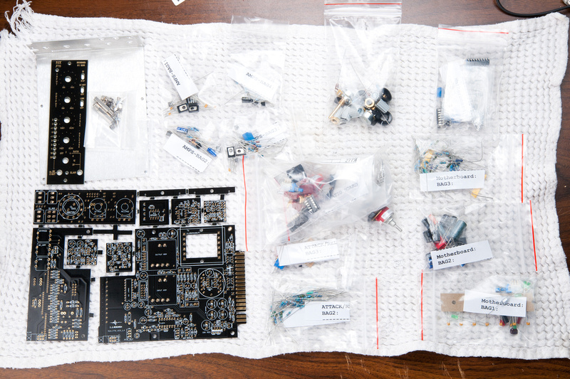
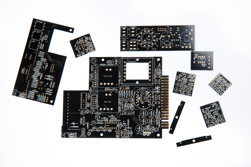
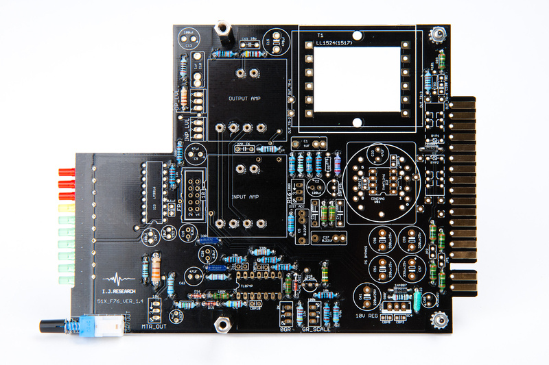
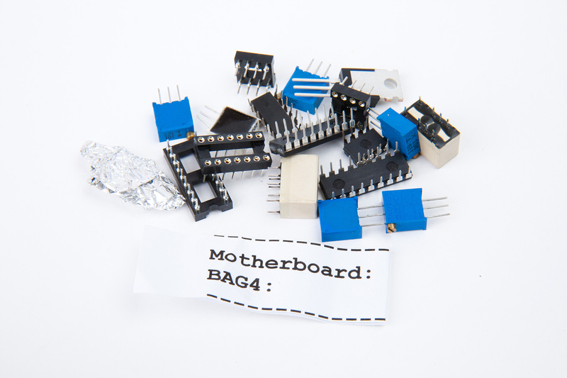
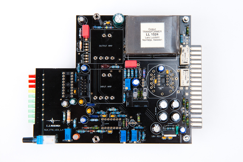
With that, here are the contents of the I.J. Research F76 full kit.
Now, we will see if this monkey can figure out how to it together. I'm sure hilarity will ensue as much of the schematics look Greek to me, but that doesn't stop me from squinting at them for a couple of days to try and get some orientation.
This is very different than the starter projects I tried before that were very defined and to be honest more geared towards production and sales as kits. If I understand correctly, Igor's main focus is manufacturing small runs of completed units for his clients but carries a side benefit of DIY availability. So, not as much hand-holding on the support side, and a different type of documentation to study. Luckily, full kits were made available, so much of the component selection (which would be difficult and time-consuming for newbie) has been done. Still, this seems to me like a big-boy project with lots of choices.
Build options:
I figure Igor has had the most experimentation with various possible configurations, so I will attempt to build to his preferred configuration and hear the unit that way . . . which I understand deviates from the classic 1176 sound but in his verbiage is more flexible and sounds "more pedigree". Everyone has different tastes and this kit has options, but I figure I'll try it this way first.
1. Balanced Line Receiver
2. I.J. Cascode input amp
3. Grayhill stepped attack, release, and ratio (as supplied in kit)
4. input/output pots (as supplied in kit)
5. Igor indicates he uses "his own" output amp. I assume this is his Albatross opamp which is not available in kit form. I will build the original output amp option as well as try an APP2520E that runs on +/-24V.
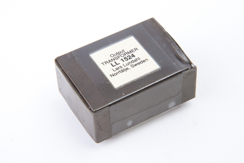
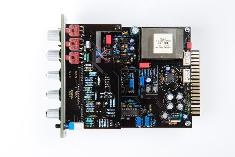
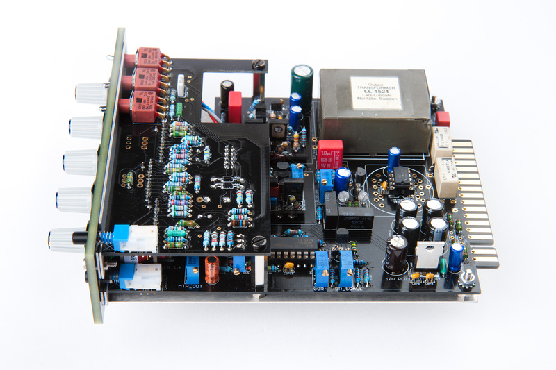
6. LL1524 output transformer (sourced through Igor's friend salvaged)
Ultimately, I would like to try all of the included amp options, but I assume I will have to buy a few more small components to build out all of the amps.
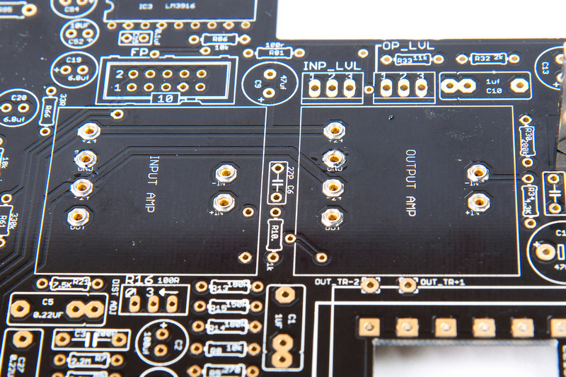
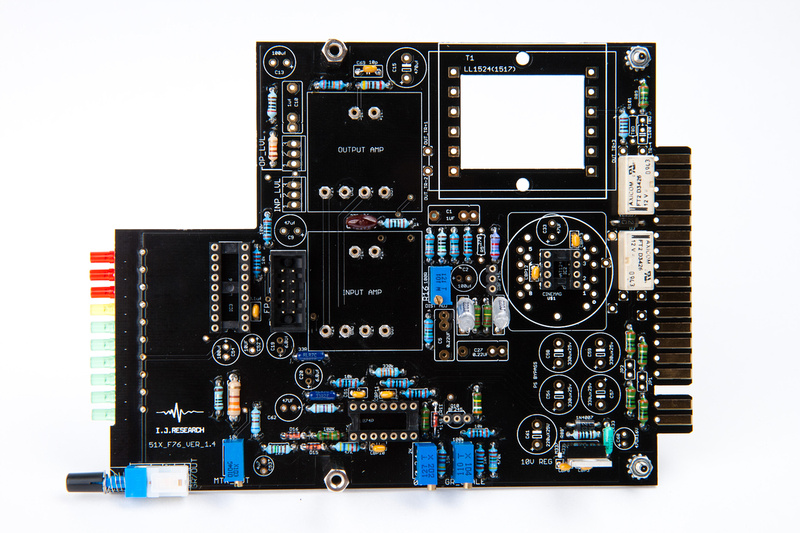
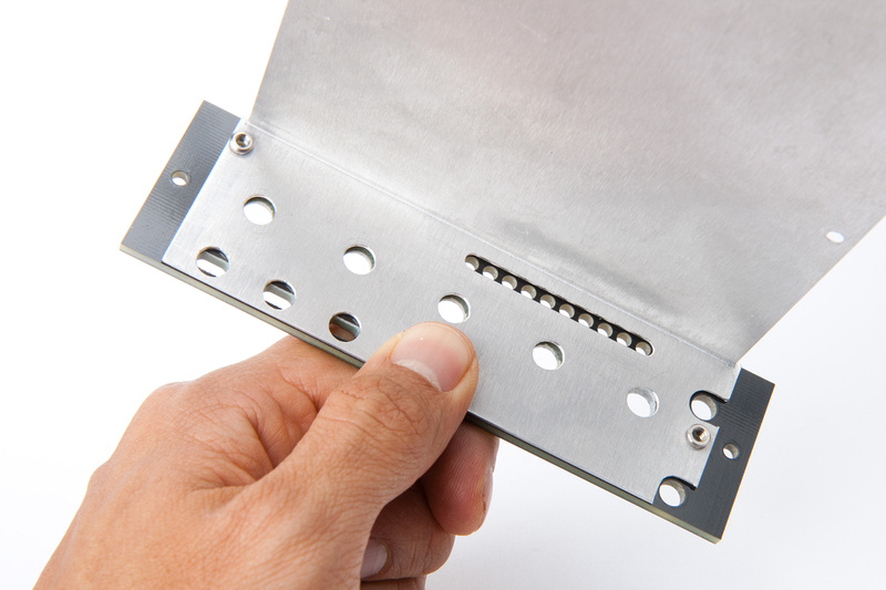
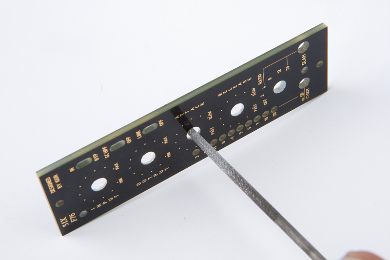
OK. . . now that I have a general idea of my build configuration, I start the build by sawing apart the PCB's and cleaning them up. I used a hacksaw blade, a wire cutter, and a file to get these separated.
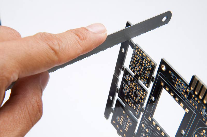
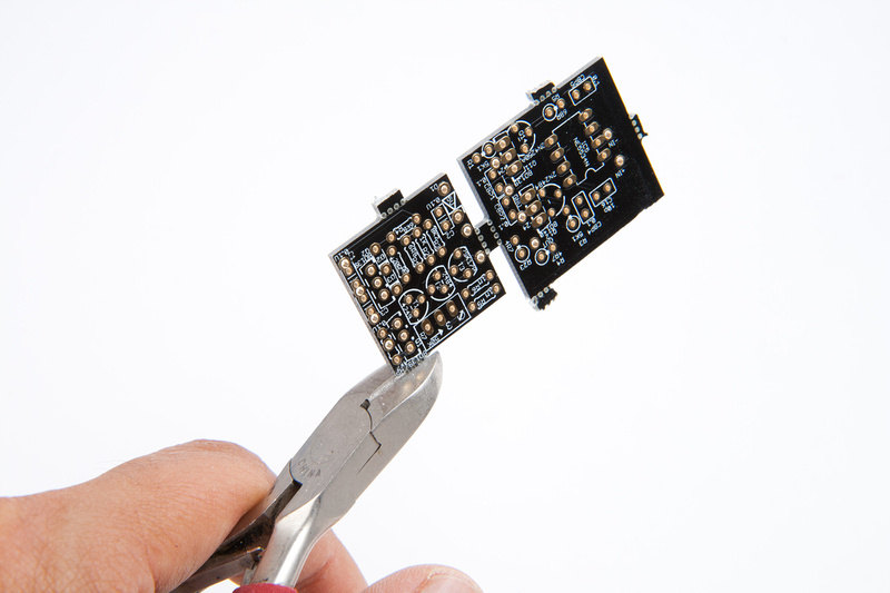
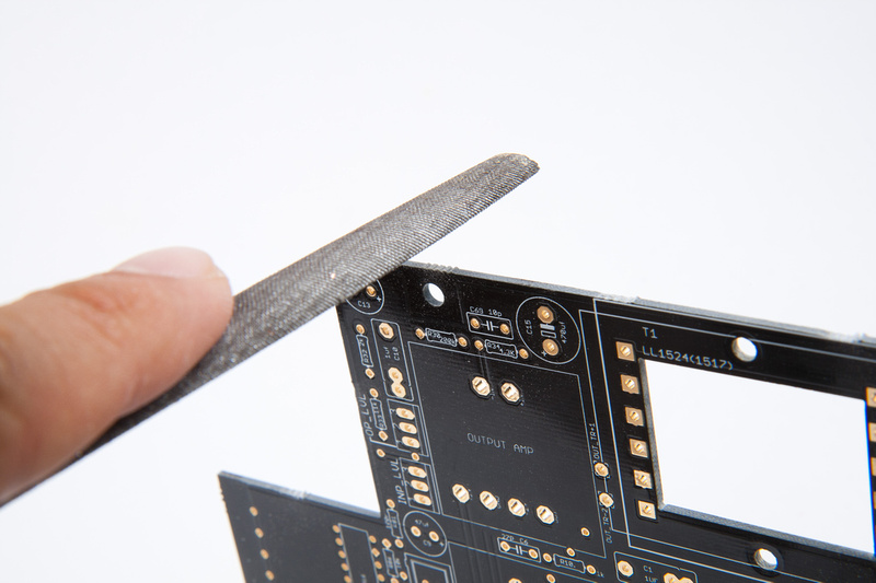
and, pretty PCB's ready to go.
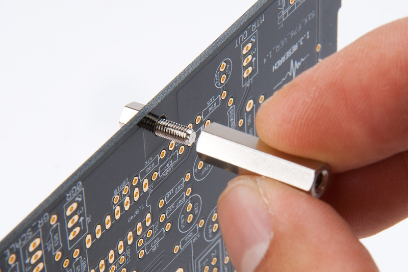
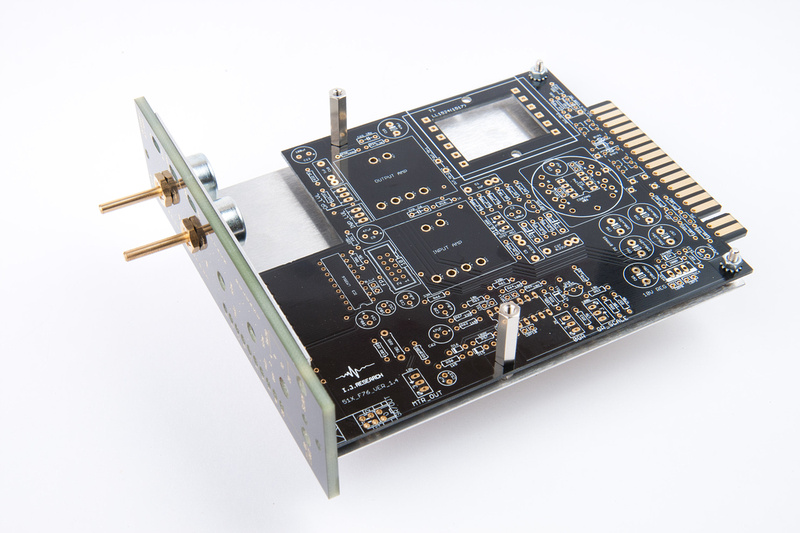
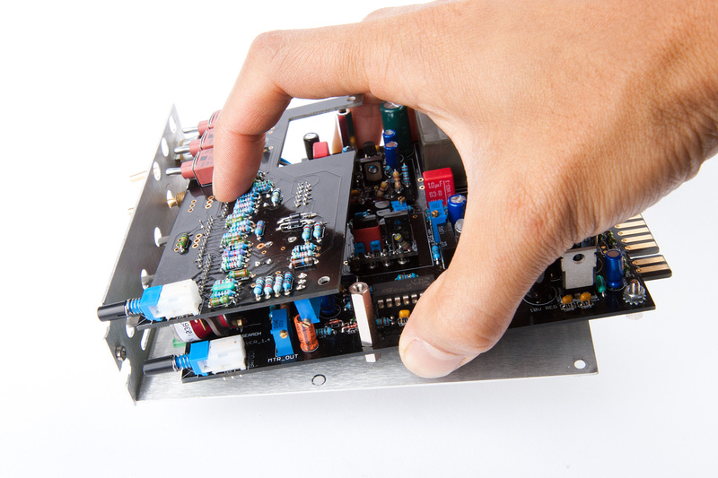
I heard rumor from a few people that there were some mechanical assembly difficulties with the kit, so I decided next, I would try to assemble the major components to discover what those difficulties are and figure out a way to shift the tolerances so the build will be as polished-looking as I can manage. I thought this might be important before I started populating the PCB's so I do not accidentally install a mis-aligned component that is difficult to remove and adjust.
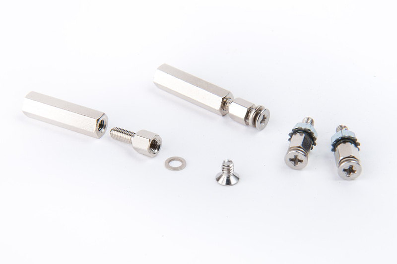
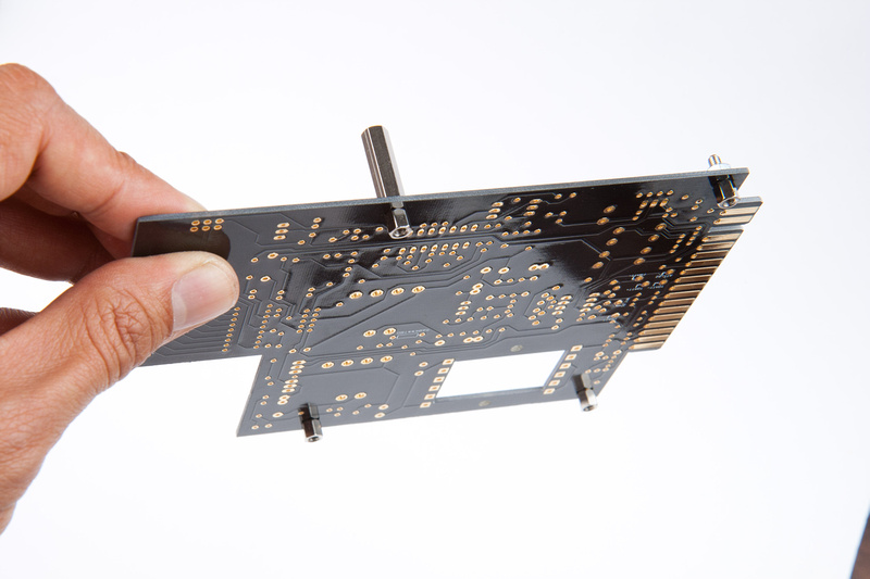
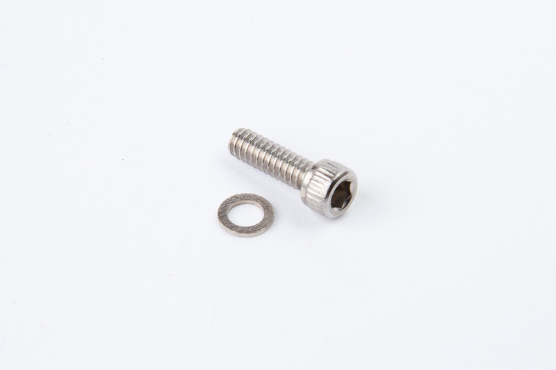
First, I located the main PCB mounting hardware.
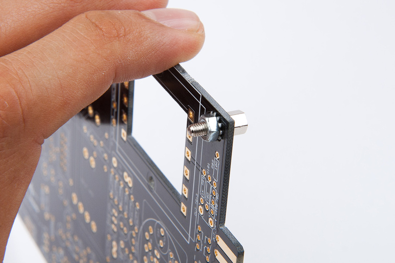
And proceed to temporarily mount the main PCB.
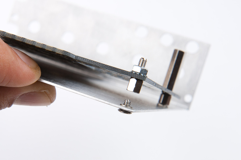
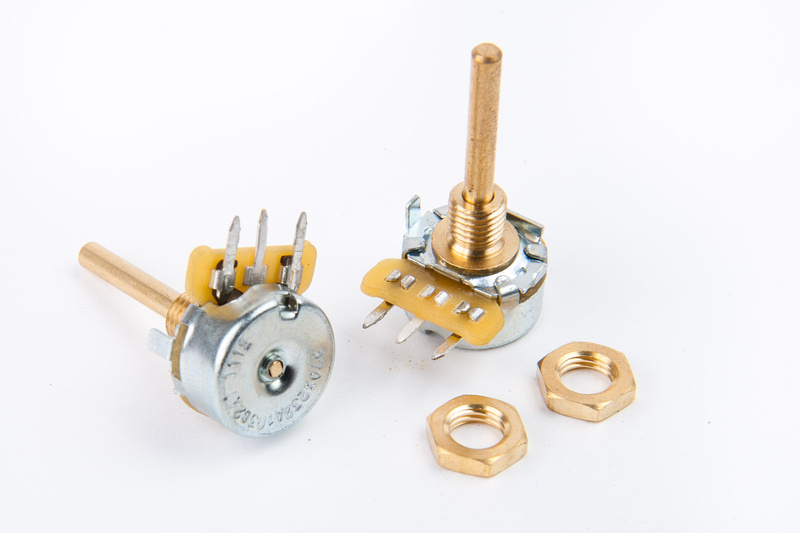
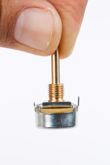
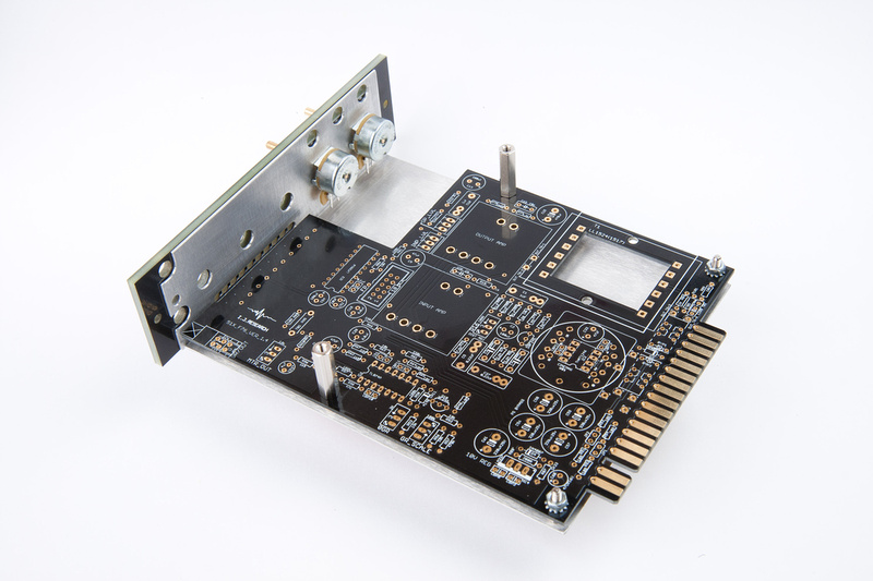
Next, I located my input and output pots along with their nuts.
And, discover that they will not mount flush to the L-bracket without slight modification.
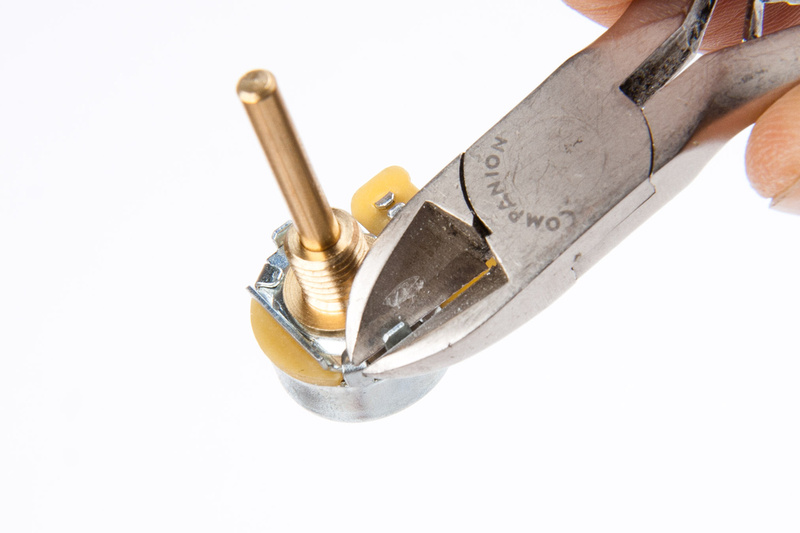
so, I modify.
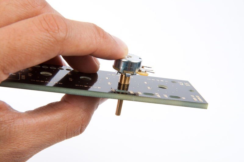
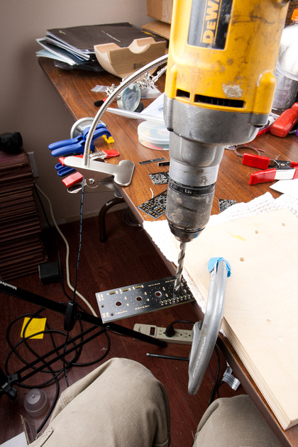
Next, I discover the pots will not fit into the faceplate. . .
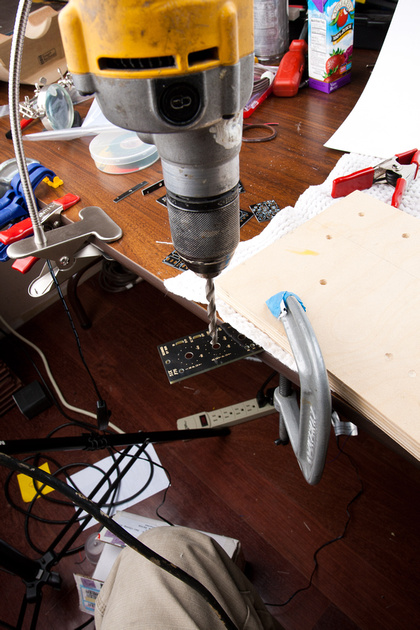
So, I use a 1/4" drill bit and open up the holes slightly. I ran my drill backwards to get a smoother cut and try not to damage the nice faceplate.
no problem now.
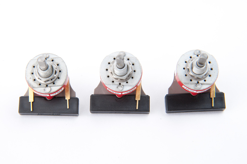
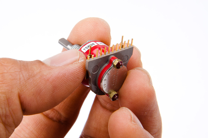
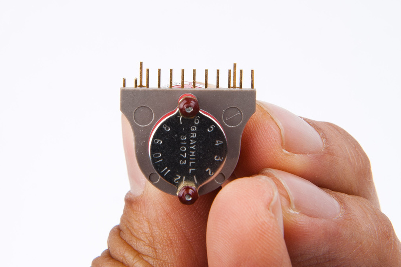
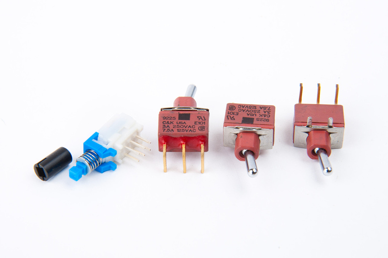
Next, I locate my grayhill switches
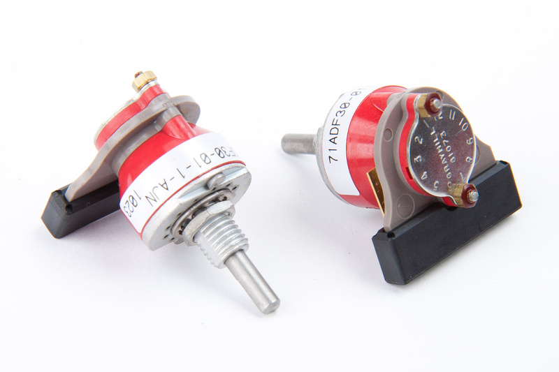
I worried for a moment that I would confuse the 2 types of switches and then realized that they have different mounting tabs. . . there is no way to install them in the incorrect locations

But, unfortunately, they also do not fit on the faceplate. . .
So, a bit more drilling for the grayhill switches.
At this point, I take a step back and decide that I should align the main PCB components before moving up to the secondary PCB and the grayhill switches, so I put the grayhills aside and concentrate on the main PCB components.
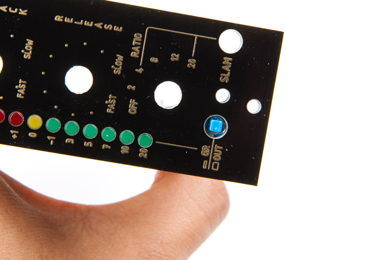
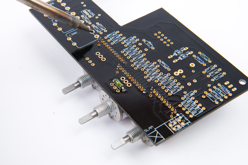
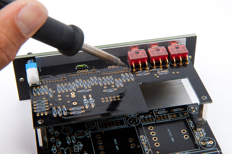
Next, I install LED's as clearly described in this thread by Igor.
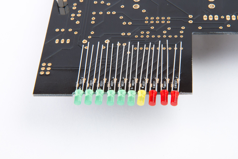
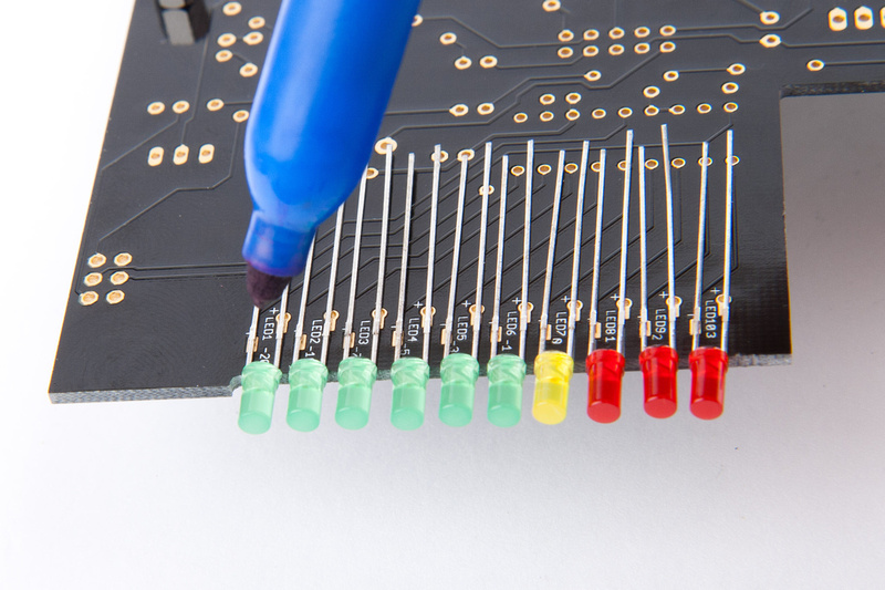
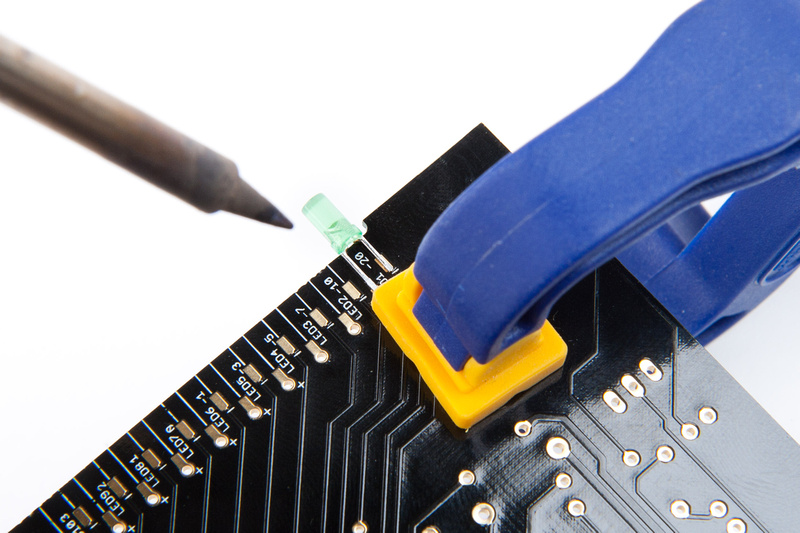
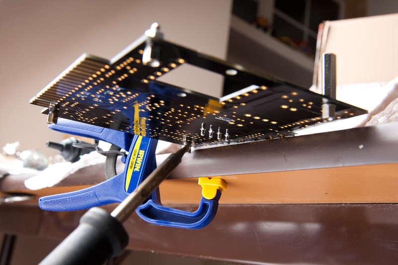
I used a clamp to help me position the end LED's for soldering.
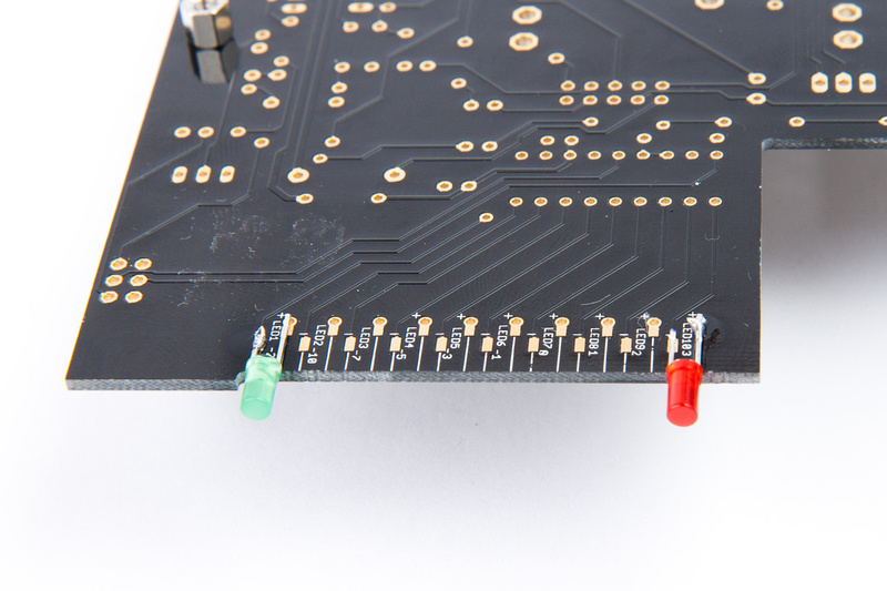
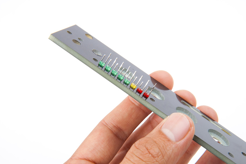
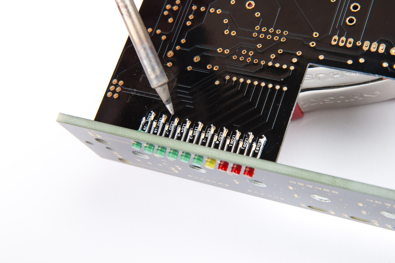
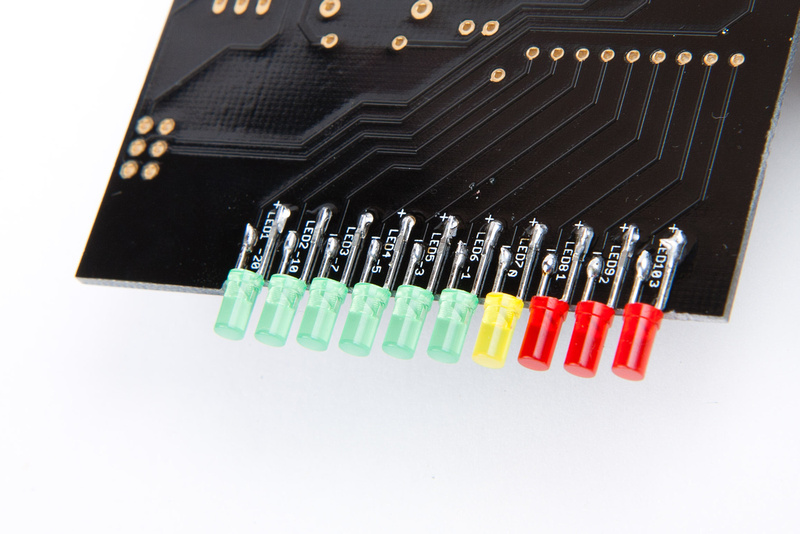
and, LED's installed.
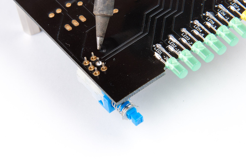
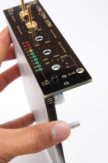
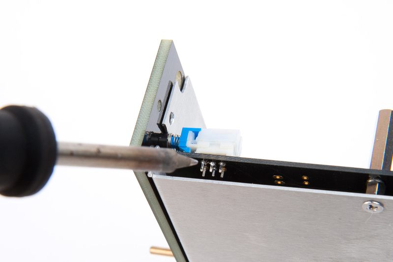
Next, I install my metering GR/output switch making sure to ONLY solder 1 pin.
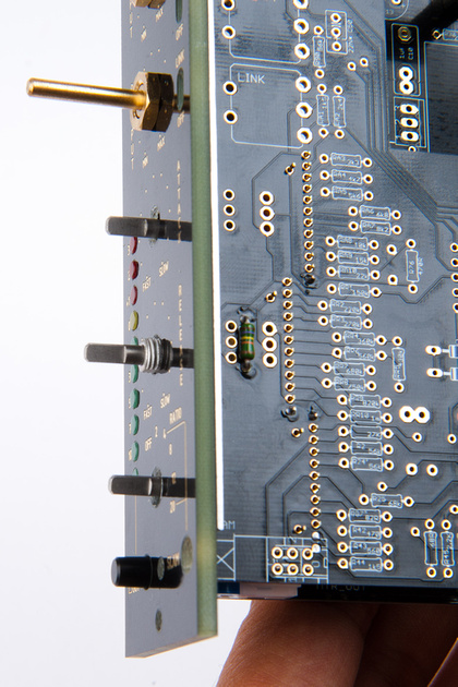
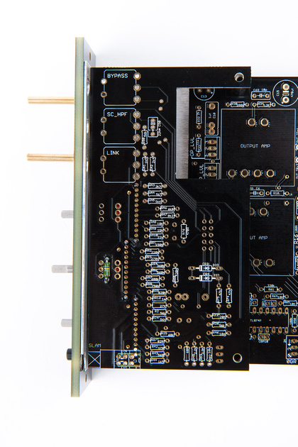
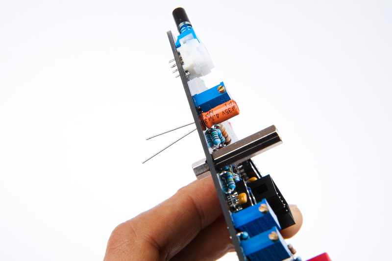
Then, I re-assemble to see how things are lining up.
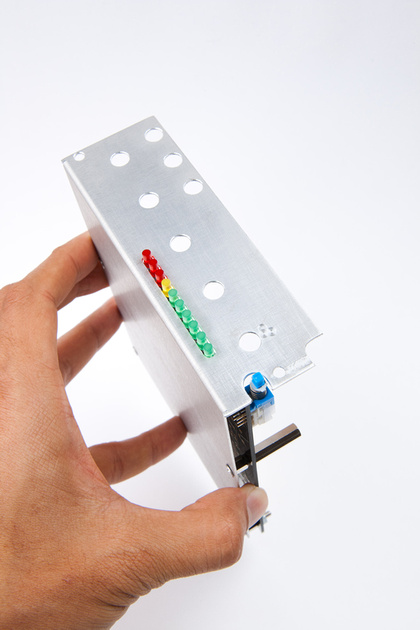
And, they are lining up poorly.
It seems the LED's are pushing the main PCB upwards a bit creating a bend, and causing the switch to move upward. The LED's are all soldered in and I do not foresee them moving easily, so I decide to modify the switch to fit better.
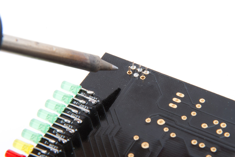
I figure I should try to compensate and make an adjustment so the switch is not installed under strain. I remove the switch (luckily, I only soldered one lug) and file the front mounting tabs.
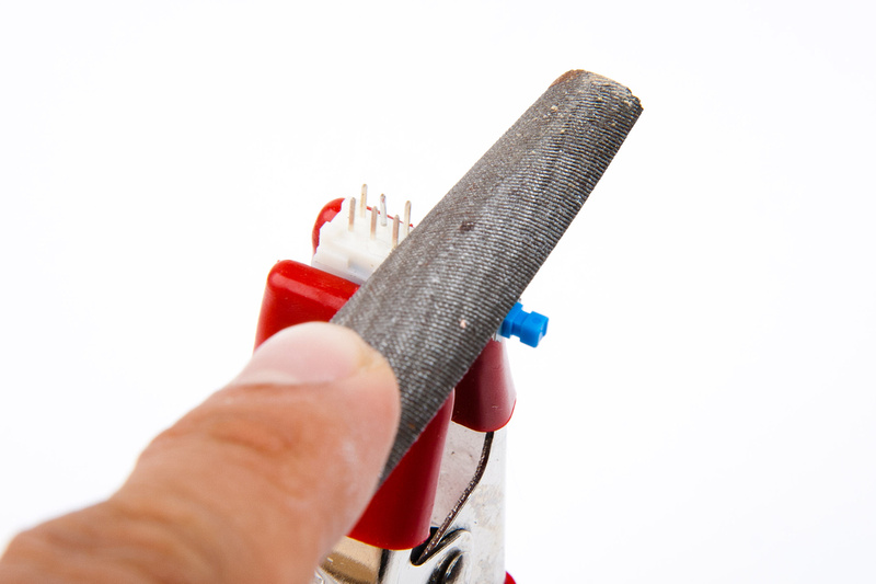
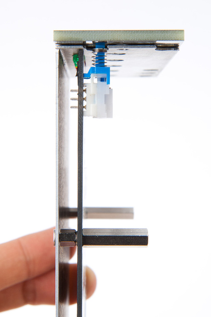
now the switch will mount in a compensated position.
I re-mount soldering again, only one lug to verify.
And, my alignment is now reasonable.
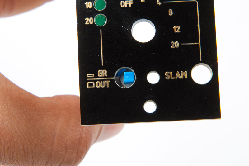
I install the external button to confirm
And then, when I am satisfied that the switch position is good to go, I solder the 3 accessible lugs in place.
Then, I disassemble and solder the remaining lugs.
Here I am for now. . . slow, but steady gets the job done right I hope. . . next, I will align the grayhills on the upper PCB.
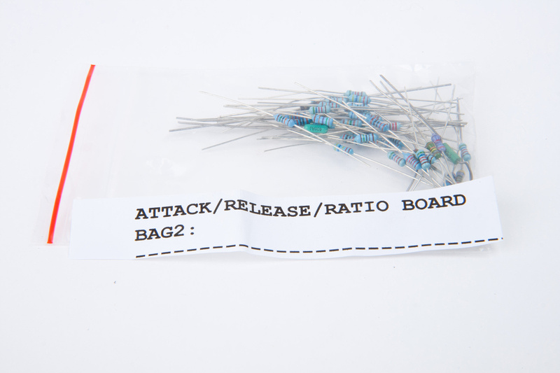
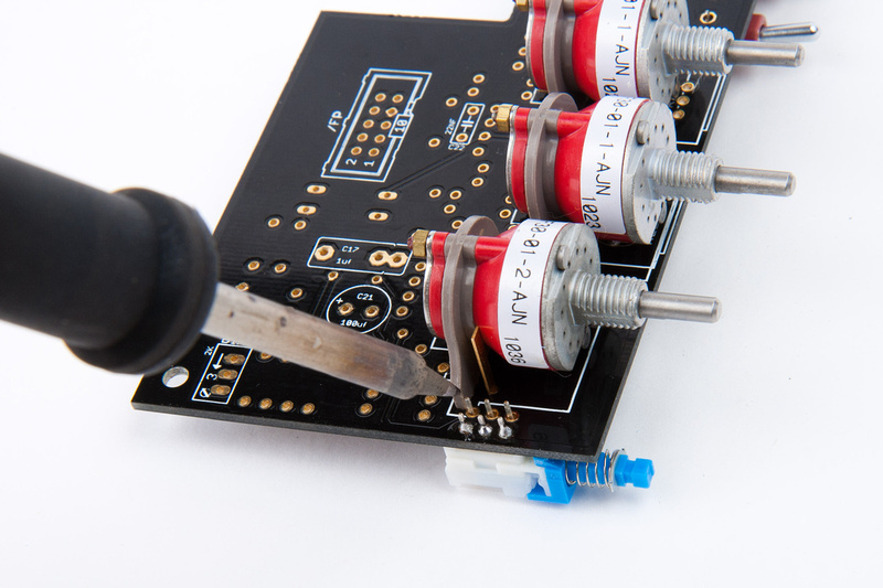
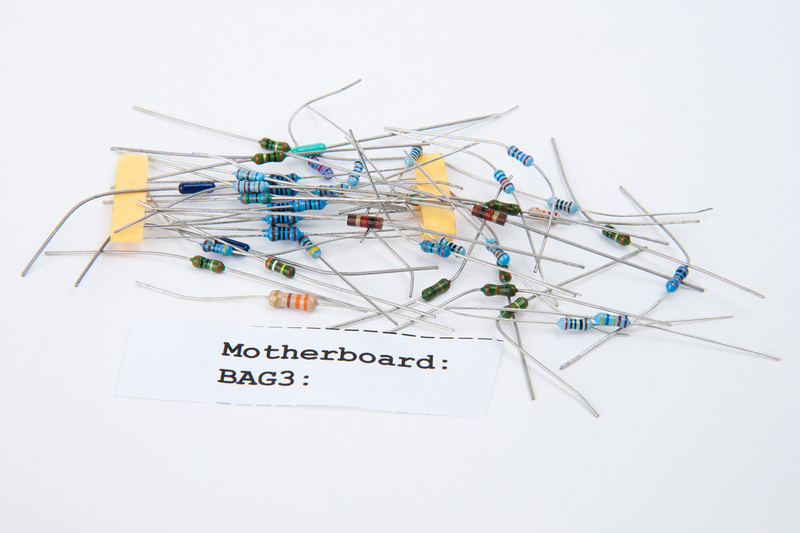
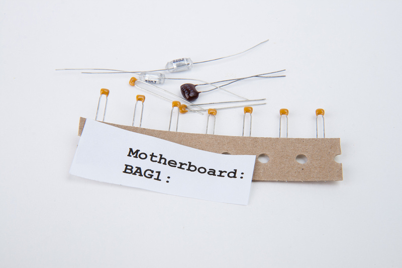
at this point in physical build, I wanted to move upward onto the chassis and place the control components of the attack/release/ratio board. When I examined the board, one resistor would prove difficult to solder after the grayhill switches were installed, so I needed to go to this baggie and find R79 (270K).
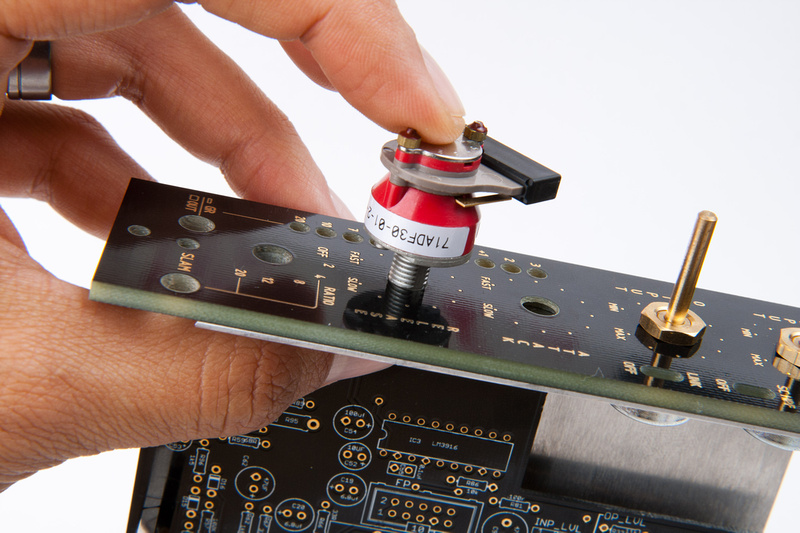
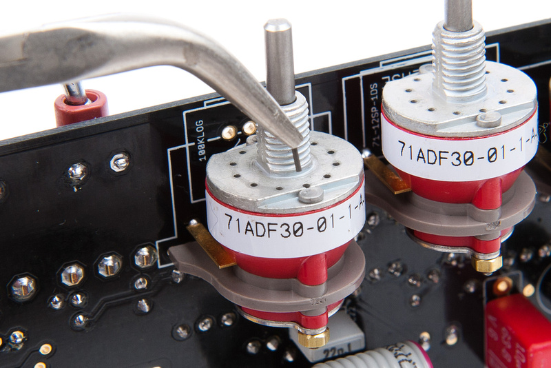
After installing R79, I went ahead and installed the release and attack switches soldering only 1 lug for easy shifting or removal so I could verify physical alignment prior to soldering more.
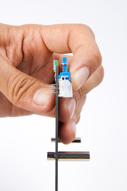
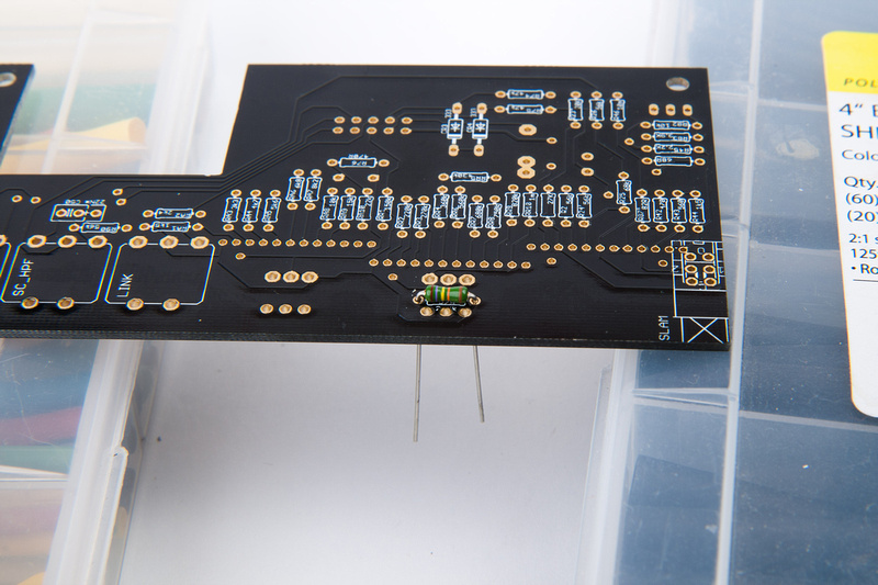
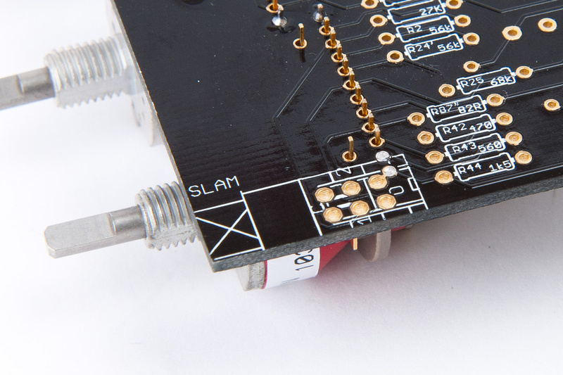
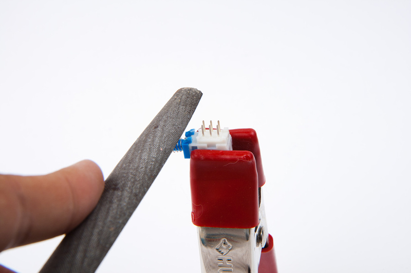
per the instructions, the ratio grayhill switch needs to be trimmed on the 2 outer legs to allow the slam button to be installed.
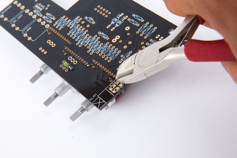
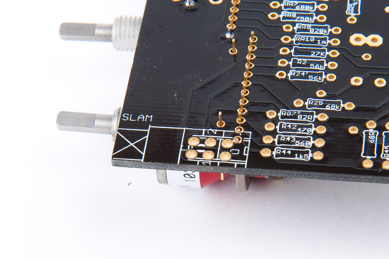
And those 2 legs can now be soldered in pretty much flush to the PCB.
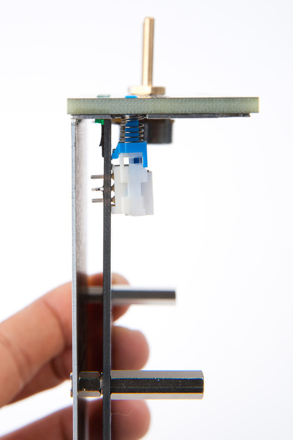
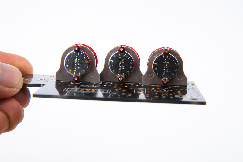
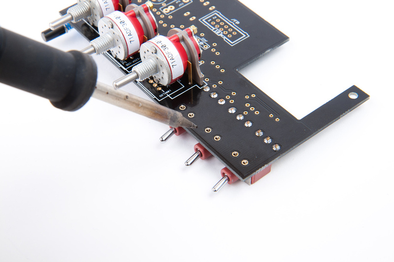
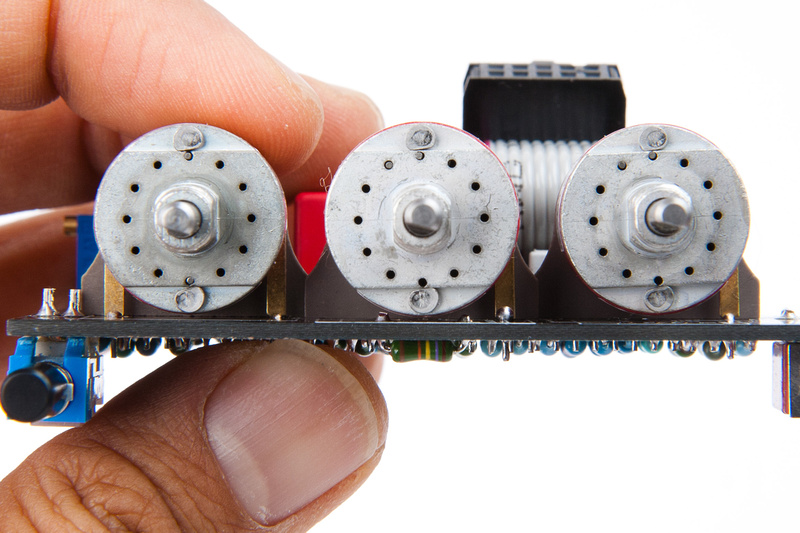
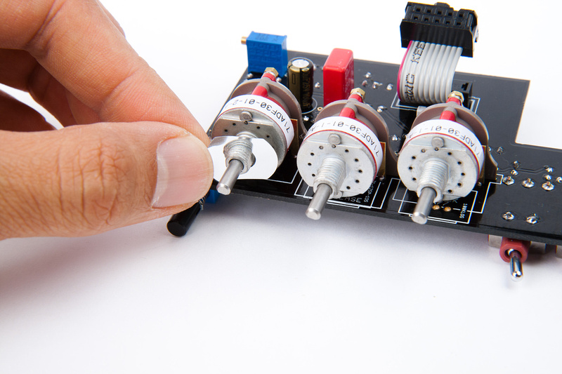
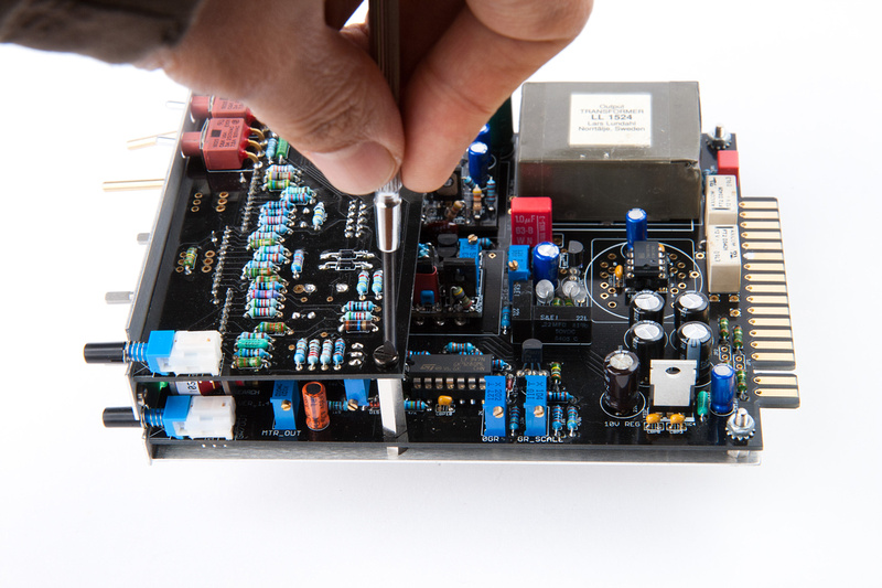
Verifying alignment of grahill switches attack, release, and ratio. Looks good. so far.
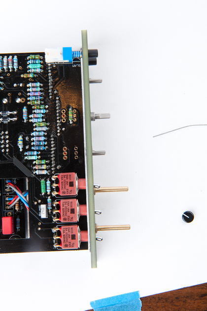
The release switch along with the input/output pots will have to have their shafts cut at some point.
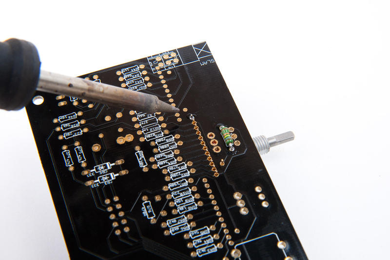
Verify the grayhill switches are flush to the PCB. . .
. . . and I solder in 1 more lug on each switch to secure the back side flush to the PCB.
Alignment is good still.
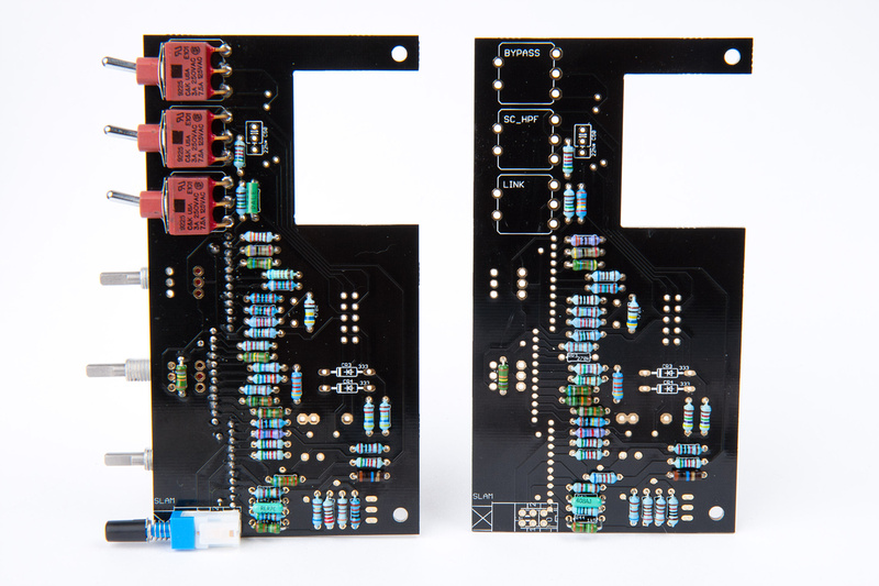
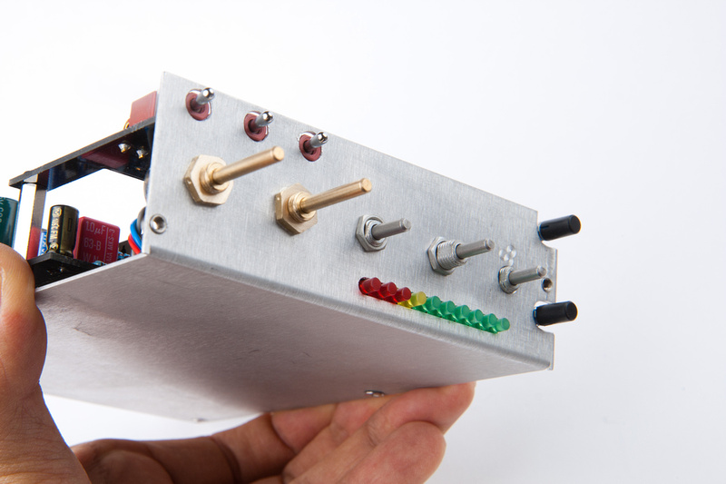
Next I pull the switches for this board.
And position them on the chassis to see where I am in terms of alignment.
Pretty good on the bypass, link, and HPF switches, but the slam switch is off a bit.
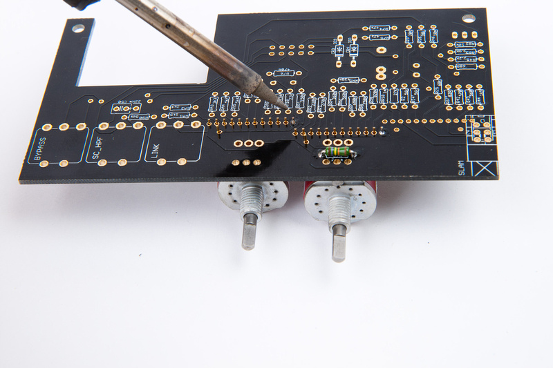
So, i file a bit on the front standoffs. . .
And, it looks much better here.
. . . so I solder from the back side.
Then, flip and solder the remaining lugs.
Next I solder all of the accessible lugs (including grayhills) with the switches, faceplate, and chassis assembled.
disassemble, flip and solder the remaining lugs.
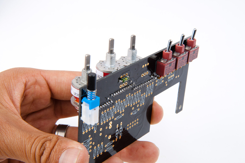
switches are all aligned and installed.
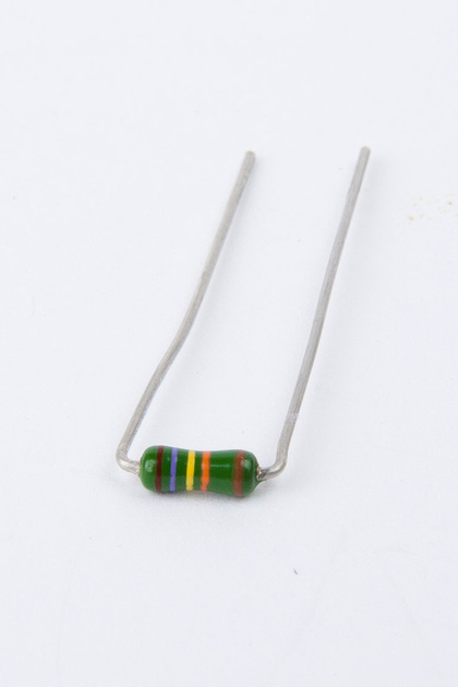
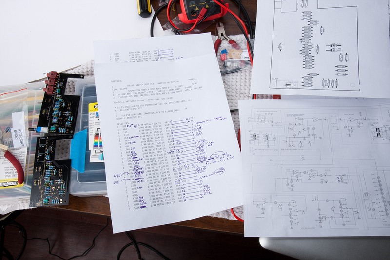
Next, I decided to stuff the attack/ratio/release board because I had it out, and was already digging through the resistors. I discovered that there were several different brands/colors/types of resistors, and further, there were value substitutions in the kit. For a seasoned electronics tech, this should not be a problem, but for a new builder like myself, this is problematic.
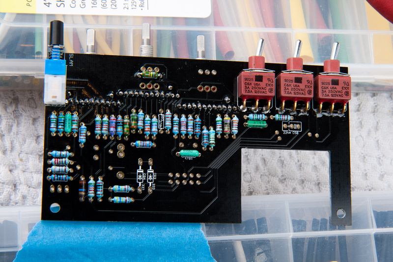
After stuffing the board, I did not have confidence enough to solder the resistors in without verifying substitutions are correct and proper. Also, I am attempting to build a stereo pair, so I wanted to confirm that my 2nd kit which due to packing mistake on the initial batch, arrived quite a few months later with different components and substitutions was not dramatically different. I tried my best to shuffle resistors around between the 2 kits and match the values but have questions about some of the changes and differences. To Igor's credit, a few of the substituted value resistors in the kit had enough spares included to cover another PCB. I need to find out if I will have to order some more parts to get the values closer, or if this is all ok, and I can solder these parts in.
R25 (68K) on the ratio switch . . . one kit has 67.8K and the other kit has 68.8K.
R74 and R75 (47K) on the detector. . . the closest resistors I found were 2x 47.5K and 2x 46.5K . I put 47.5K into the first kit and 46.5K in the second kit because the schematic looked like these resistors may need to balance within the circuit.
RA9 (15K) one kit has 14.69K and the other 15.05K
R42 (470R) was substituted 464R in both kits.
R76 (470R) was substituted 462R and 464R.
R79 (270K) the kit supplied these as 274K, but I am missing one. Kit cannot be completed without.
Should I re-order any of these resistors to find closer matches? or is it ok to solder? I will wait until confirmation before sticking these components together.
This is a bit frustrating for me chasing values around the documentation instead of moving forward with assembly. In the end, I went to a local electronics supply store and picked up a few of the values that were to my eye most mis-matched and soldered everything in noting my precise values in my notes in case I needed to re-visit the portion of the build later on.
At the time, I was a bit frustrated, so I thought an input amp build might cheer me up a bit. . . please note, The kit only provided enough parts to assemble one input amp and one output amp. If planing to build all of them, some additional parts would need to be purchased. I wanted to try a few of them out so I will attempt to note and purchase the parts that I need to complete all of the amps.
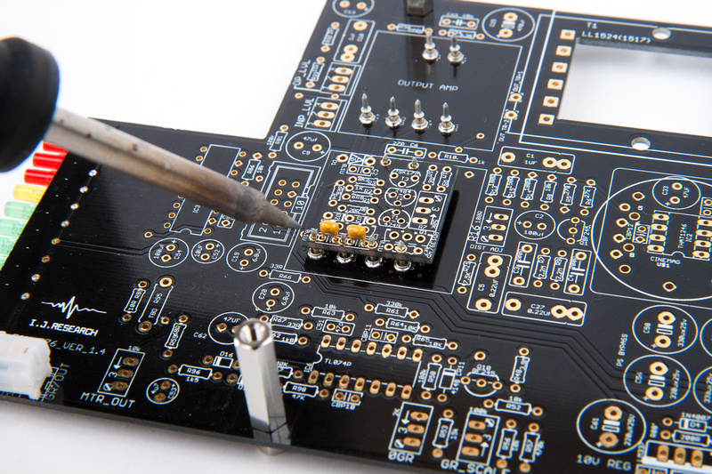
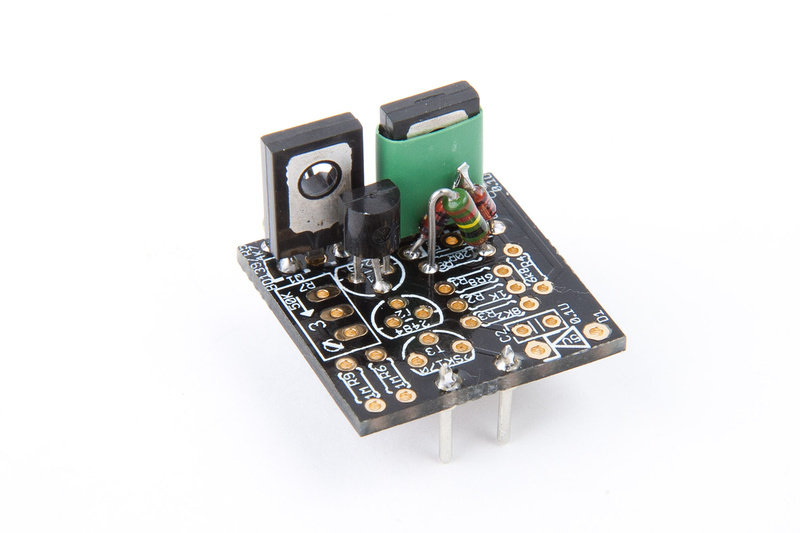
I figure I'll start with the Igor's input amp and started by putting the Mil Max sockets in. Your methods may be different and better, but this way got the job done.
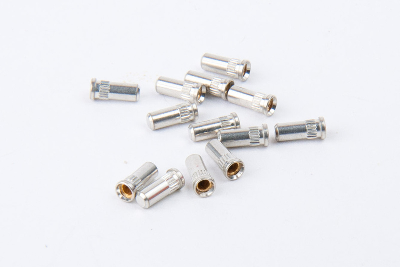
I was hoping with the little ridges on the sides that there would be some sort of friction fit on these to hold them in place for soldering because I was afraid to get solder on the inside of the sockets and have them seize up, but these are very small and very loose, so my plan of attack changed to soldering these in from the bottom and hoping gravity would keep the solder from flowing up into the sockets.
I had to re-heat and press down on the sockets to make them seat properly, but it seems everything worked out ok.
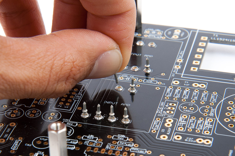
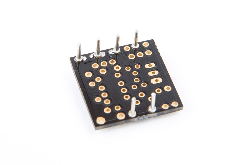
Then, I inserted the milmax pins so I could have them aligned nice and straight when I solder them to the amp PCB.
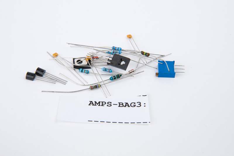
AMPS-BAG3 contains the components for Igor's input amp. . . I hope.
The holes for C1 and C3 were very close to the milmax pins, so I thought I should insert them prior to soldering the pins just in case I got solder overflow and ended up plugging up the holes and making a mess.
And, this is how I solder on the pins.
I did have to clean up the solder joints for the capacitors from the bottom, and I probably didn't have to install them at the same time with the pins, but better safe than sorry, eh?
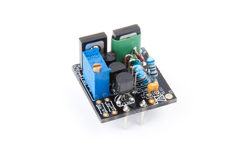
And, we're populating.
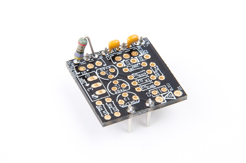
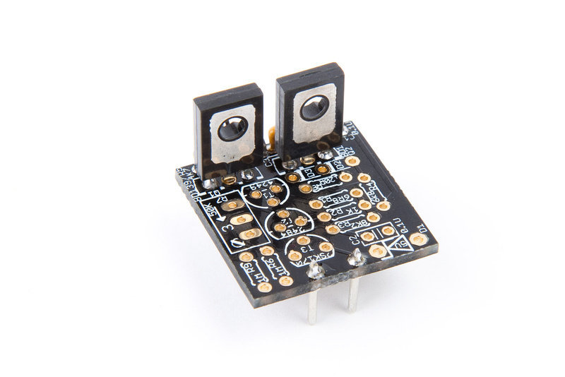
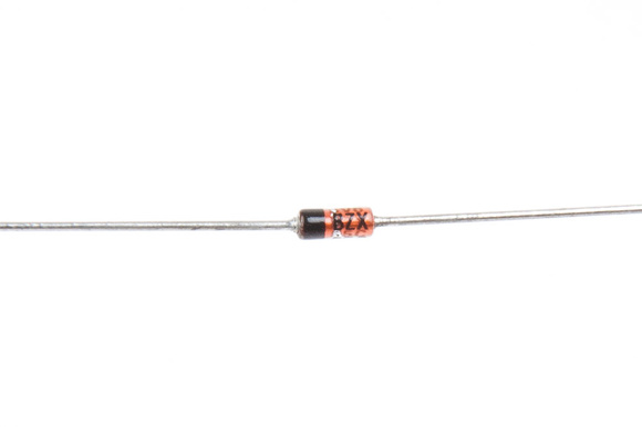
A little piece of heat shrink tubing over Q2 helps to keep D2 and D3 from shorting against the metal part.
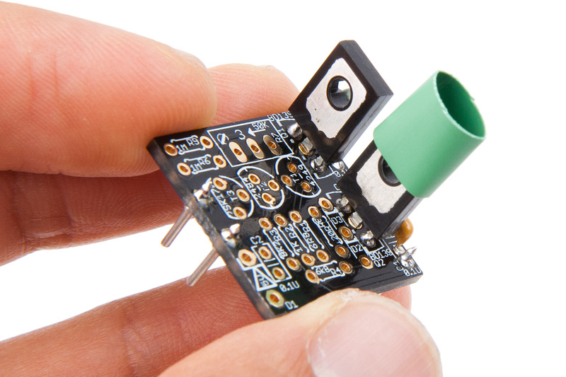
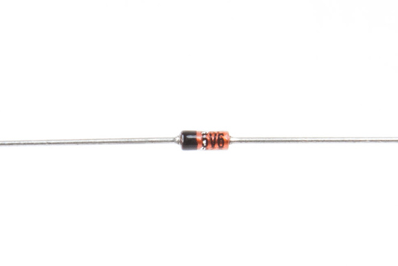
D2 and D3 are marked like this:
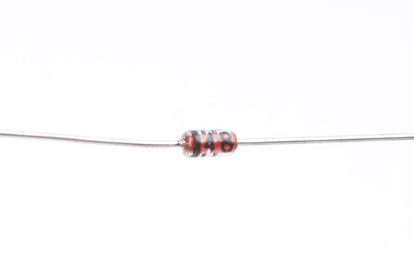
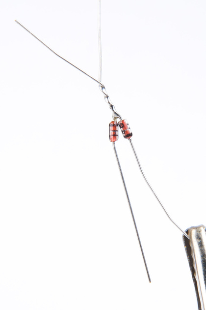

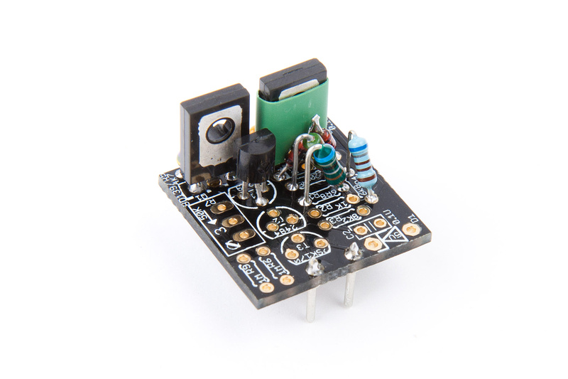
D1 has the following markings:

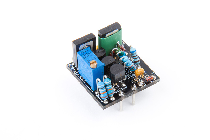
And that completes this input amp. There is a modification that Igor suggests for "tasty sound" that I may try on this amp as well, so I should put that resistor on my shopping list, but for now. . .
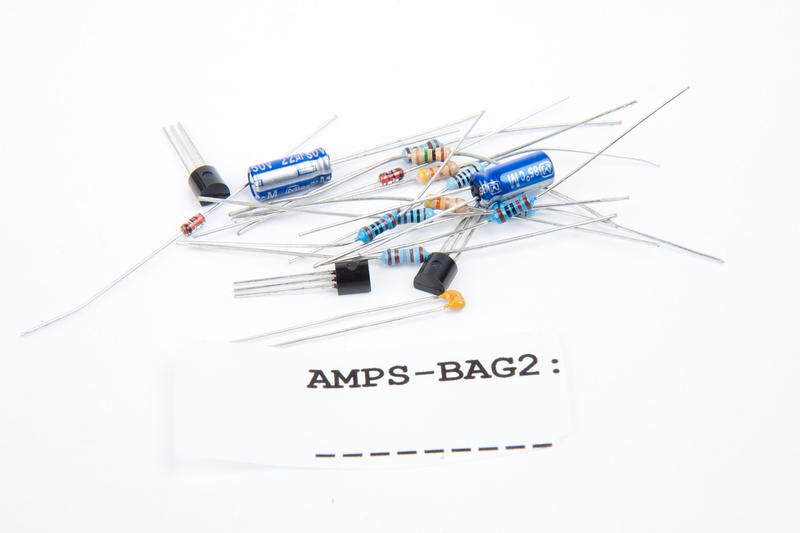
Original output amp (AMPS-BAG2) "steals" the following components from (AMPS-BAG1. . . the IC output amp bag):
1x 10p ceramic capacitor (10J)
1x .1u ceramic capacitor (104)
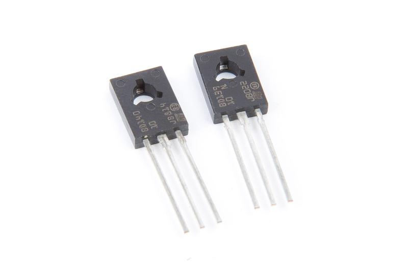
1x BD140 transistor
1x BD139 transistor
if building all amp options, these components along with extra Mil-max pins will have to be purchased.
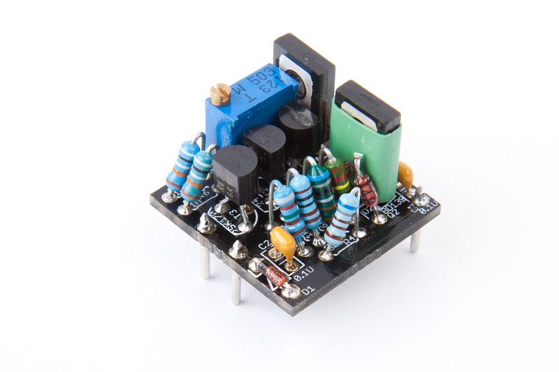
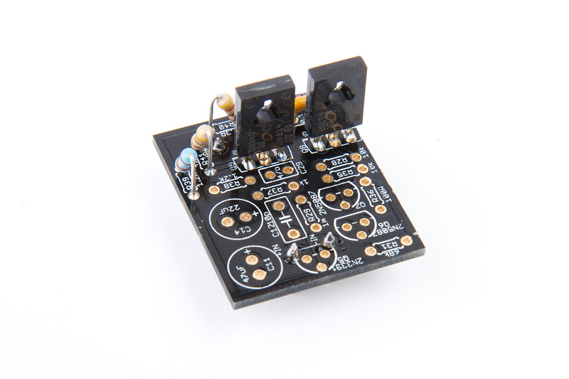
On to output amp. . . I chose to build the "original" amp. . . largely because I do not own a vintage or clone 1176 and wanted to hear what the original was all about. . . distortion and all. My gut feeling is the IC output amp may give better sonics, but I have a pair of APP2520E that can run on +-24V. In the original application (VP312DI), preferred the GAR2520, so I can use these in the f76 builds if I like them. My plan is to order parts to build all amps in this kit and hear them. Contacted Igor about his Albatross op-amp that he prefers as well. Options. . . no point having them if you can't hear them for yourself

For this step, I refer to the following files in the documentation:
orig_outamp.txt (component list)
orig_outamp.png (schematic)
orig_outamp.gif (PCB top view graphic)
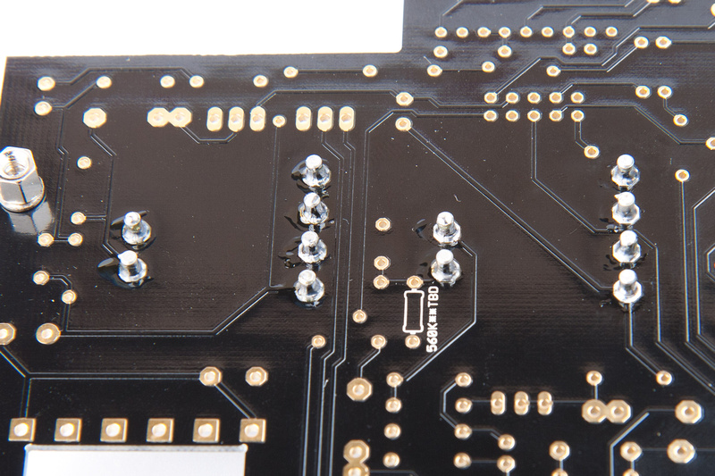
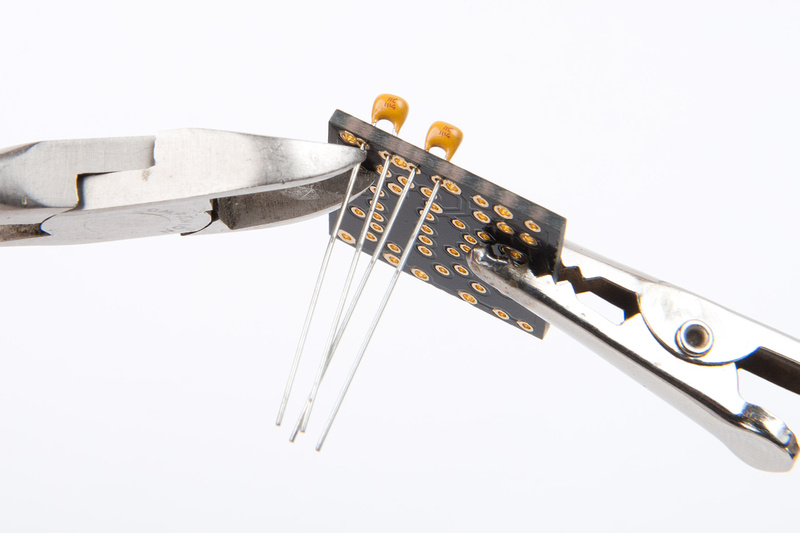
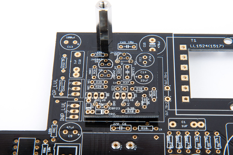
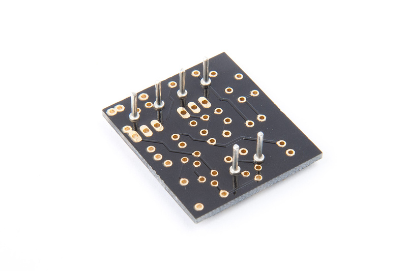
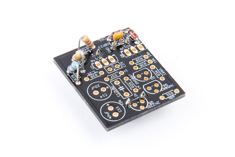
First, I use the main PCB to align the Milmax pins and solder in this position.
Most of the components for the "orginal" output amp are found in AMPS-BAG2.
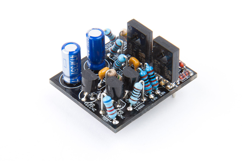
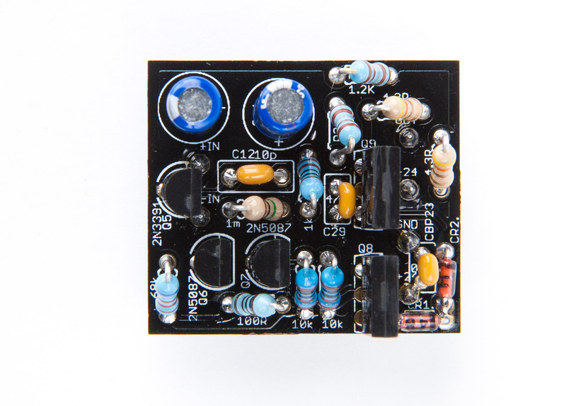
And, I begin populating the board:
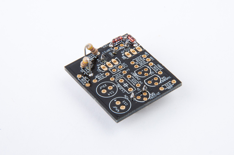
Note: in the next step, CBP23 (.1uf marked 104) is taken from AMPS-BAG1.
Note: in the next step, Q8 (BD139) and Q9 (BD140) are taken from AMPS-BAG1.
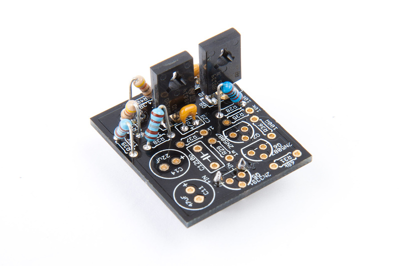
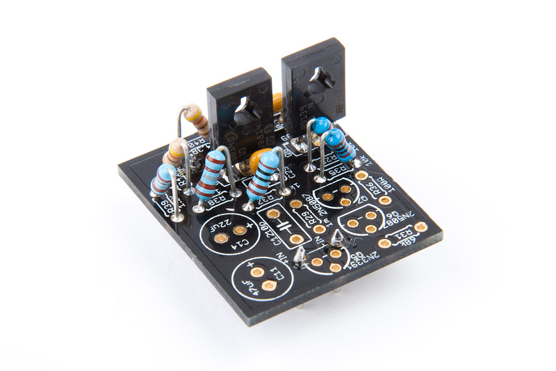
Note: in the next step, C12 (10p marked "10J") is taken from AMPS-BAG1.
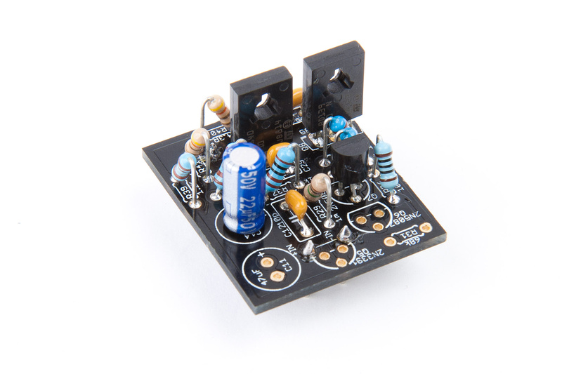
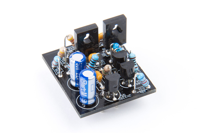
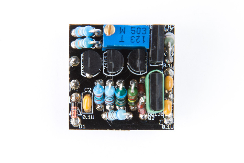
And, the "original" output amp option is complete.
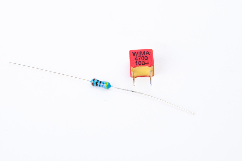
for the zobel network in the LL1524 output transformer, I'm using 4n7 WIMA capacitor and 460R resistor. As I understanding it, higher value resistor and lower value capacitor will induce less treble roll-off. Igor concurred that these were the values he utilized on his builds. I will have to wait for parts to arrive from Mouser, but for now. . .
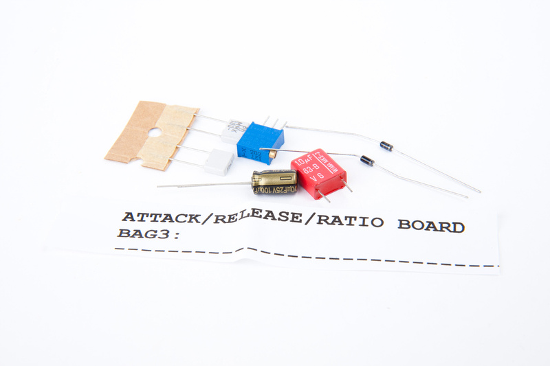
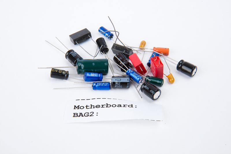
back to the attack/release/ratio board. Capacitors will be found in this baggie.
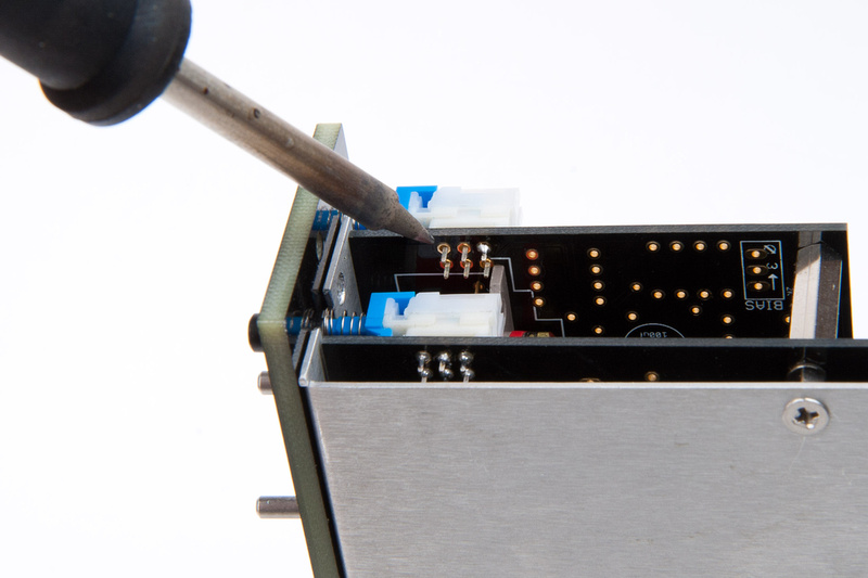
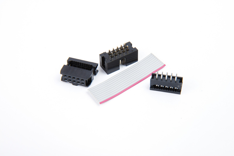
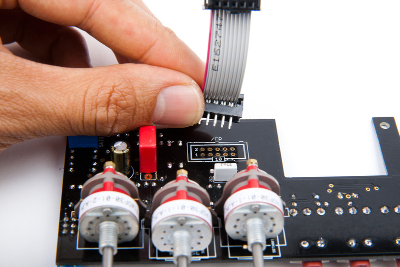
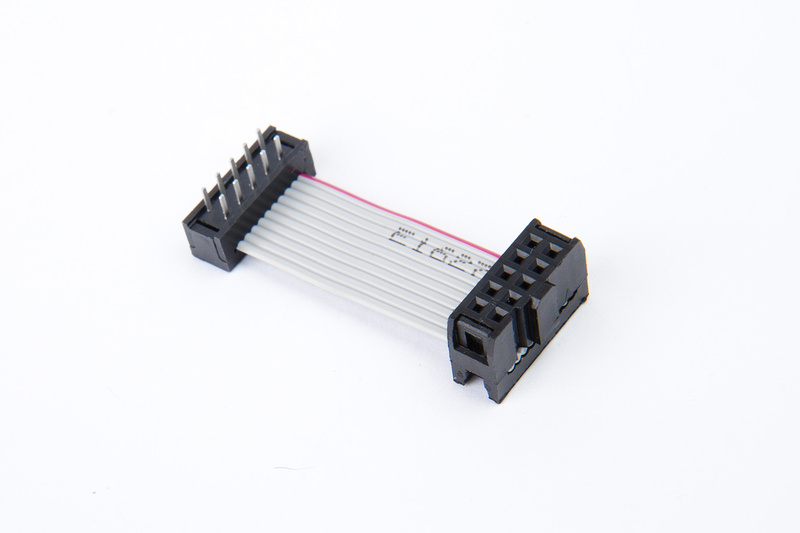
Next, I assemble the interconnect cable for the attack/release/ratio board.
The trick here is to always be aware of pin 1's position and to make sure the red-marked cable corresponds to pin 1. The PCB is marked for pin 1.
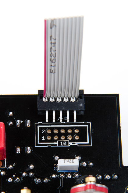
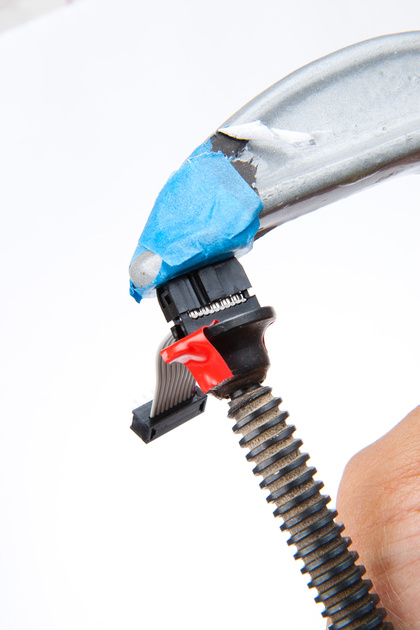
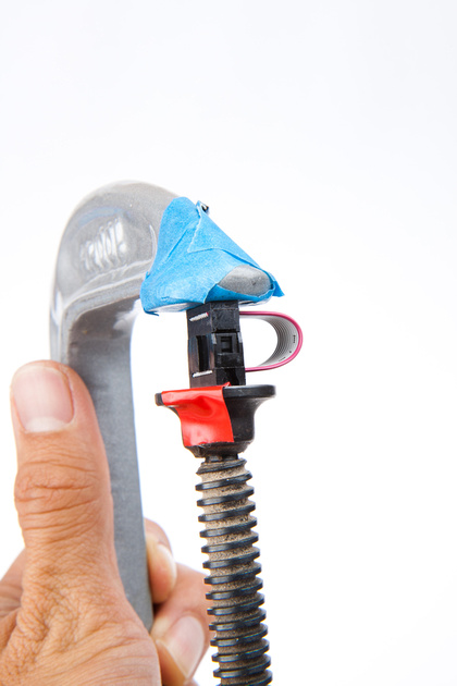
I used a C-clamp to seat the press-fit cable ends.

After double checking the proper cable positioning and pins are in the correct locations via multimeter, solder the cable to the attack/release/ratio PCB.
Next, I locate the Grayhill switch stop pins and retaining stickers. Watch out. . . they're tiny. Now is no time to let things roll off the table.
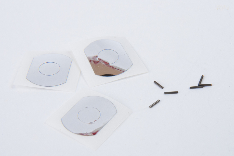
Per the documentation on the front end of this thread, insert the pins into position.
It should look something like this when all the pins are in.
And, place the retainer stickers to set the pins.
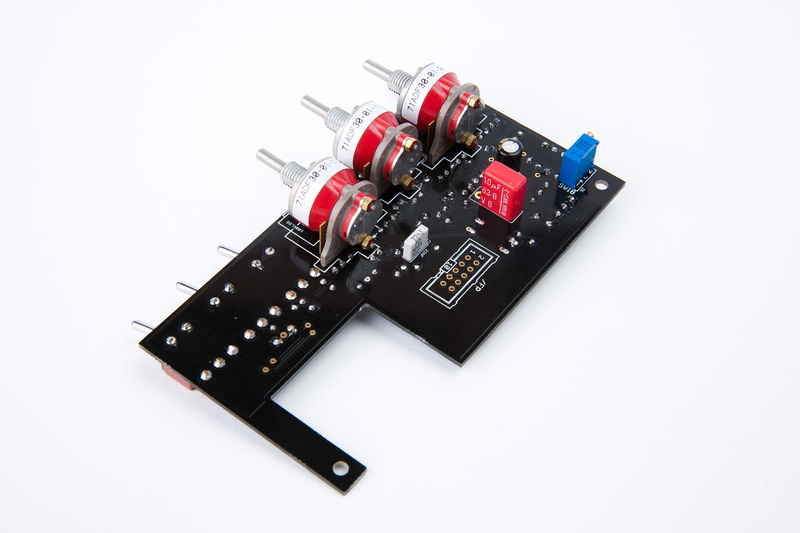
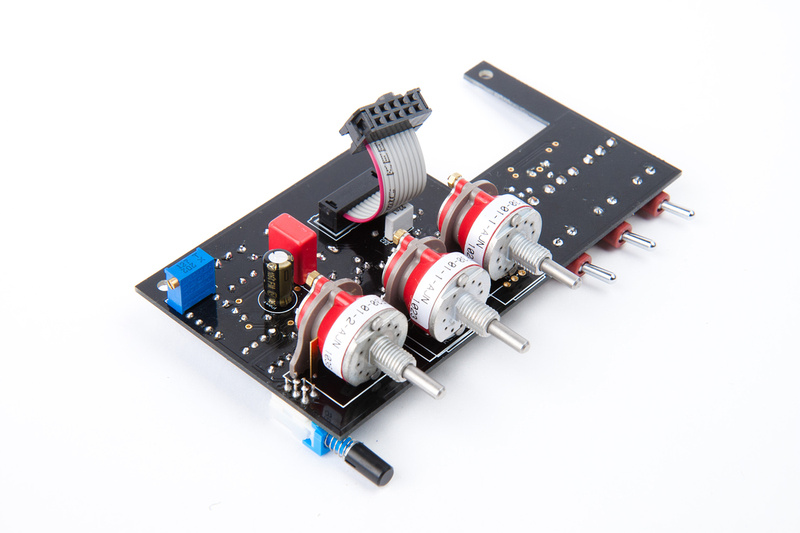
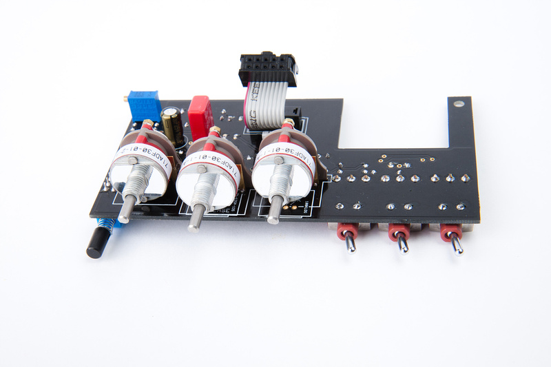
Attack/release/ratio board is now complete.
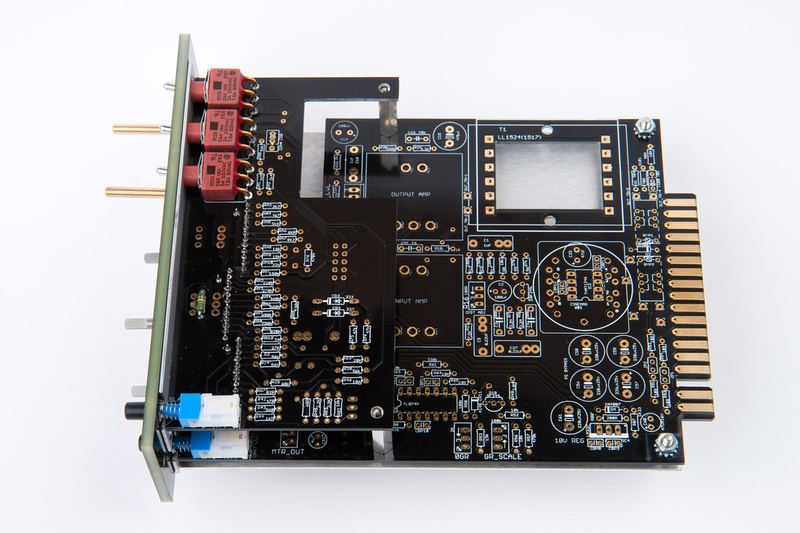
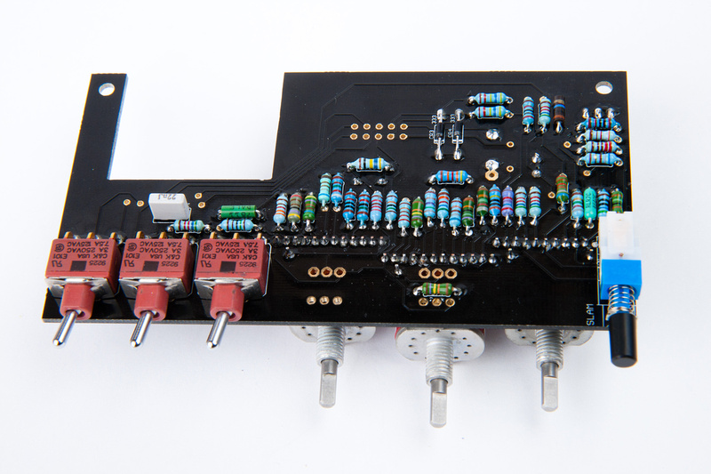
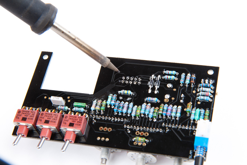
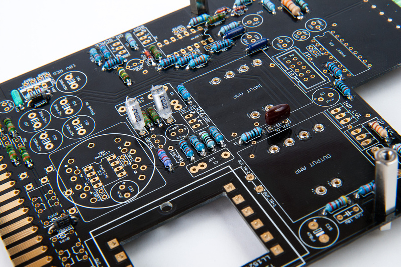
Next, I decided to do the main PCB resistors. Note, because I'm building with the IC line receiver, I do not install R5' 270R.
And the the main PCB capacitors
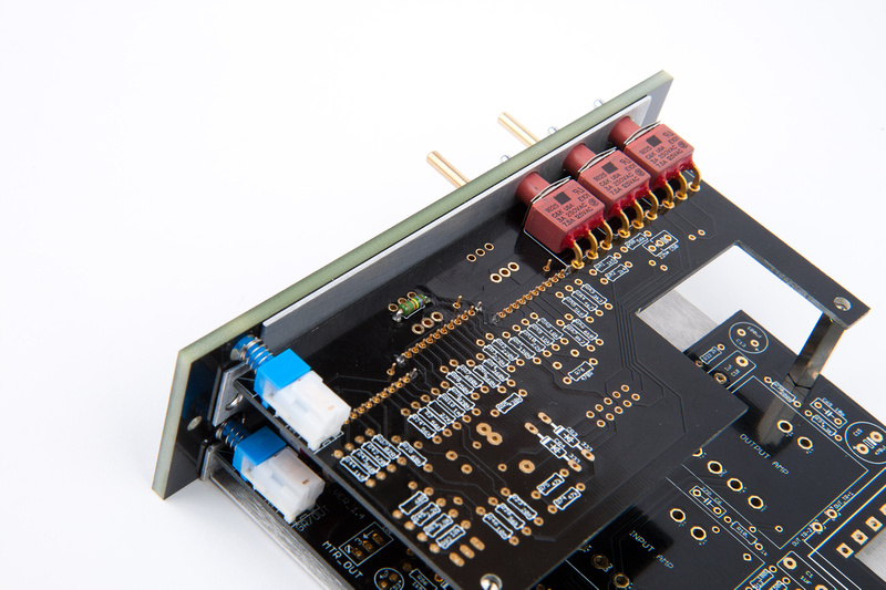
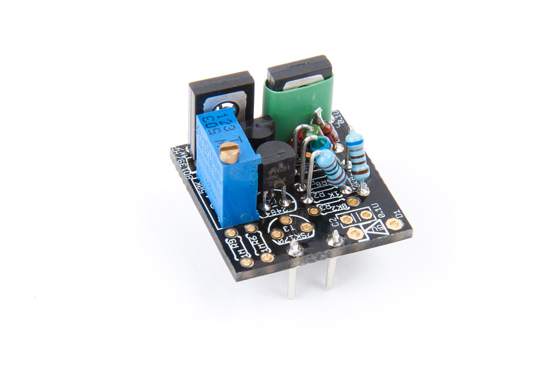
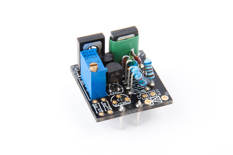
Next up were the IC sockets, trimmer pots, and relays.
And, more capacitors. . . watch out for polarity on these guys.
This cap did not have any polarity indication except for the long leg (+).
The + side of these little guys are indicated by markings. . .
Make sure they correspond to the markings on the PCB when installing.
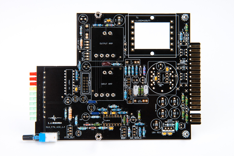
And, capacitors are in.
I purchased a pair of salvaged LL1524 output transformers from Igor's friend, and they were shipped with my kits. . . they probably didn't know which ones were going in for photo shoot. There are a few dings on them, but hopefully they have been fully tested and passed muster.
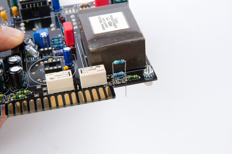
I don't think it's completely necessary, but I put a couple strips of electrical tape here.
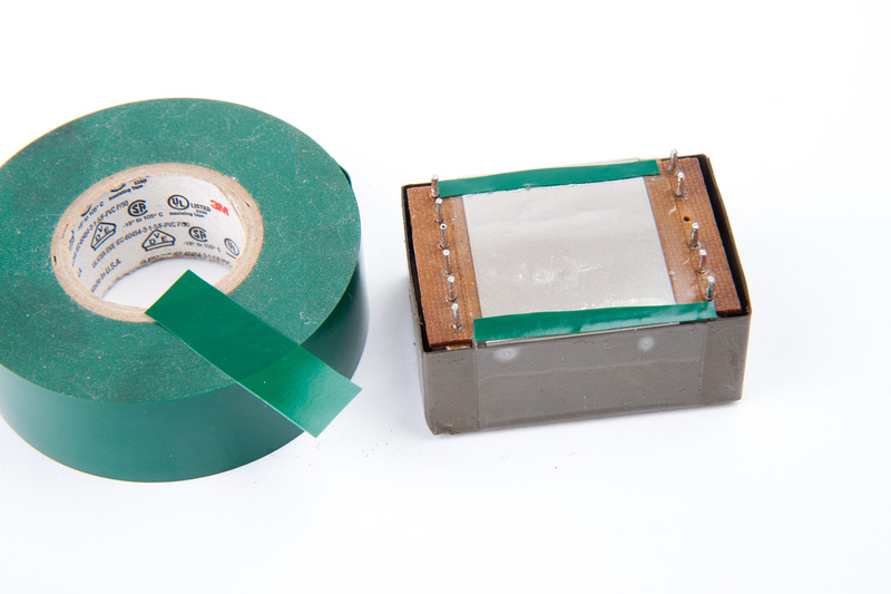
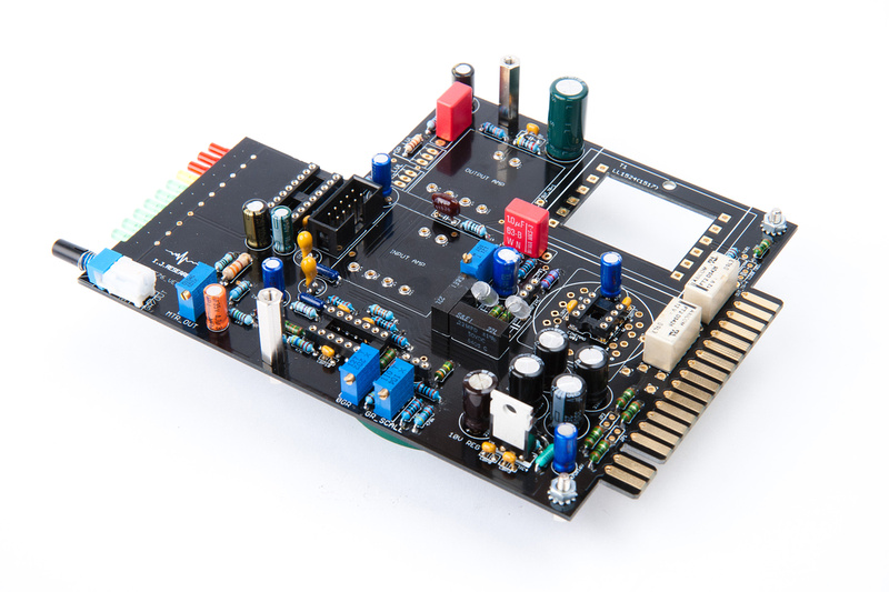
And soldered the transformer in.
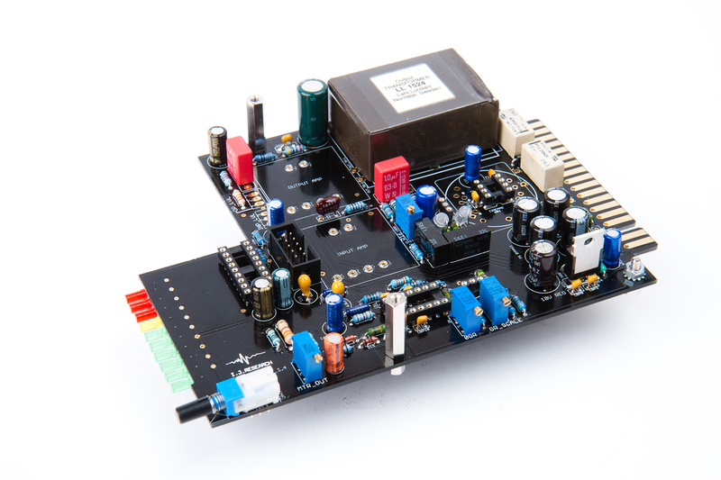
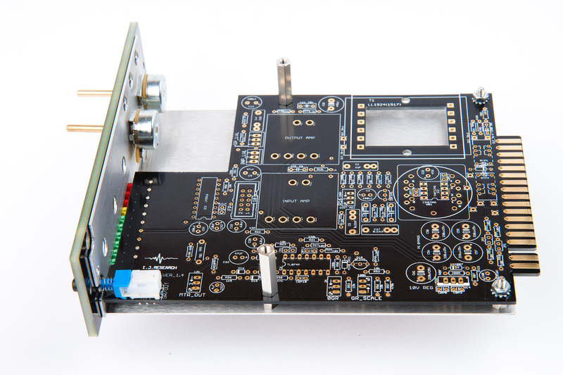
And, that's where the project stands. . . just one resistor and one capacitor left for the zobel network, and I can do final assembly and calibration. I borrowed a scope and a signal generator from a friend, so I'll have to learn how to use those funny tools in short order.
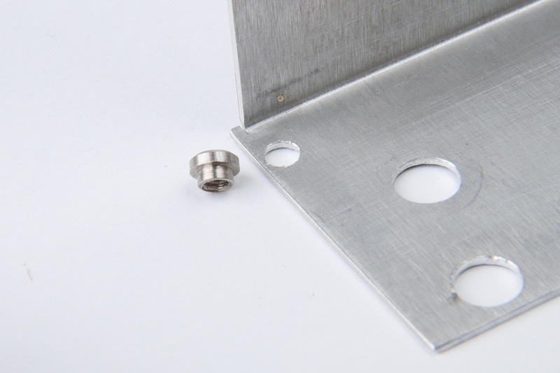
I had a misunderstanding about the nut locations on the aluminum L-bracket, but I was able to sort them out. The nuts for the pots and grayhill switches seat underneath the faceplate in the machined recesses. So, there are a couple of threaded inserts and hex screws that hold the faceplate on. These did not readily fit into the holes completely. Since the location would be very difficult to tighten, I figured I'd just try and press them in.
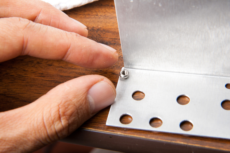
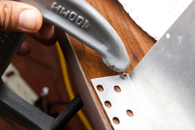
Boom. . . works like a charm.
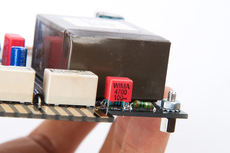
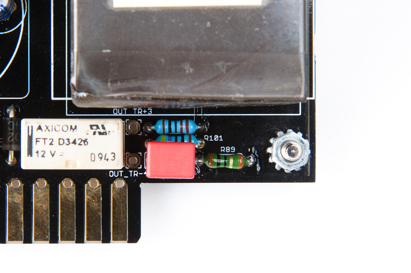
Next my Zobel network resistor and cap. R101 and C100. As I understand it, the higher value resistor and lower value the cap, the less treble attenuation will happen, so I went with those ends of the recommended range.
R101 469R
C100 4.7nf
The cap I ordered is wider than the PCB was designed for, so it did not fit very cleanly, but I think this should hold up ok. I really don't feel like delaying this project anymore.
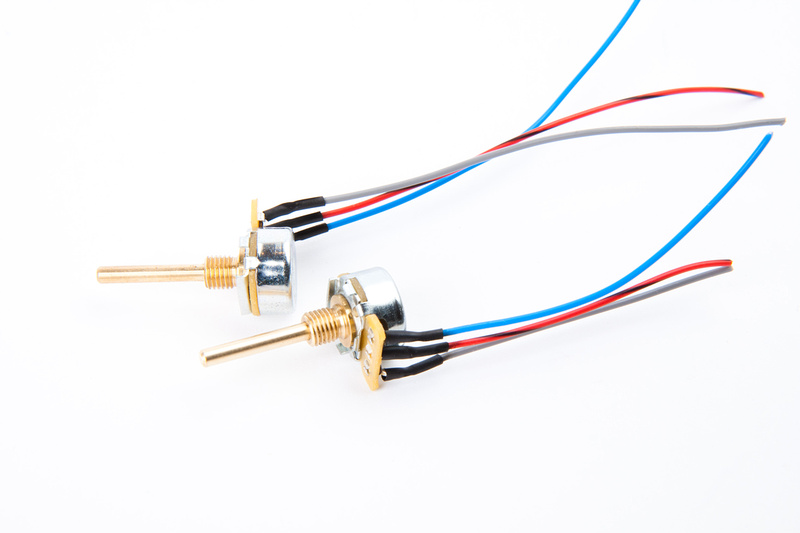
Next, I soldered a few leads onto the input and output pots.
. . .and connect to the PCB.
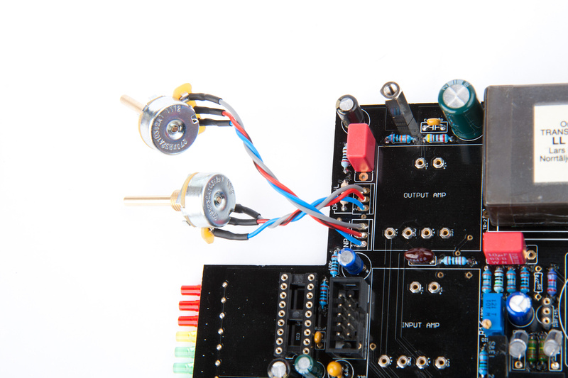
Next, per the build instructions in the 1st 2 posts, I connect my link lead just in case I use this as linked pair.. .
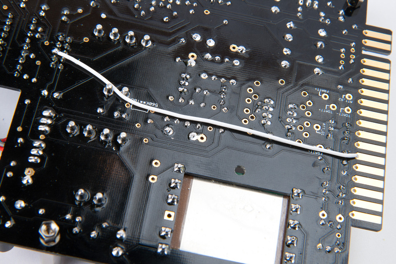
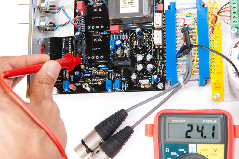
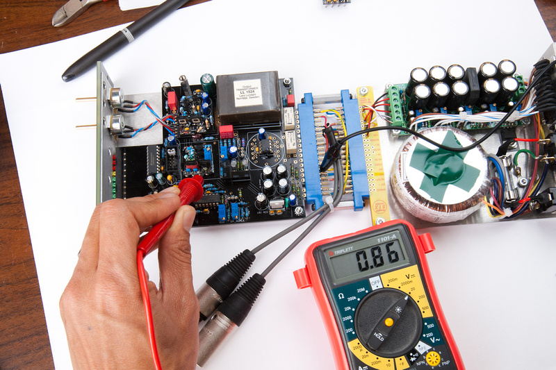
And, it looks like I'm ready to apply power and do my 1st round of voltage checks.
 Ran into some problems w/ my input amp upon initial testing . . . hopefully Igor can help me find the cause.
Next, I connect the F76 to my testing power supply which is JLM powerstation supply all of the correct 51X spec voltages.
No smoke! Humans win!
Checking voltage at LM337. I am looking for -10v here according to test procedure. I guess -9.7 isn't too bad?
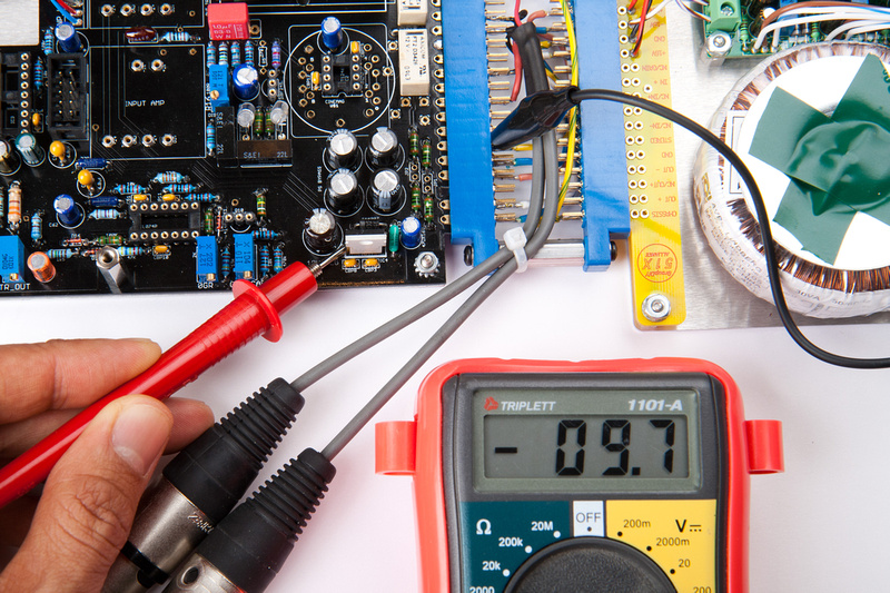
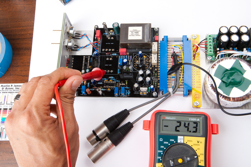
While I'm here, I might as well poke around a few of the other power points and check to make sure amps will be happy.
Installing test jumper
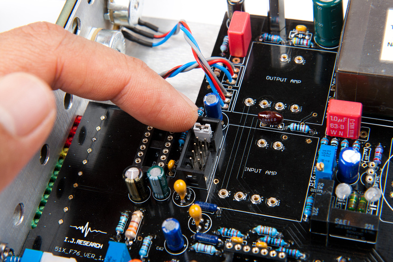
Installing main PCB IC's
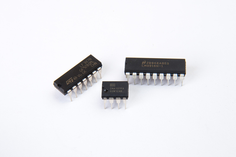
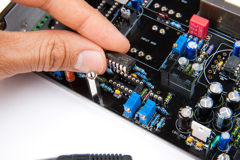
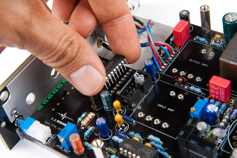
Output amp goes in.
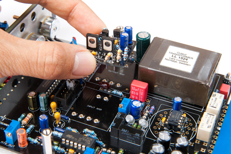
Input amp goes in.
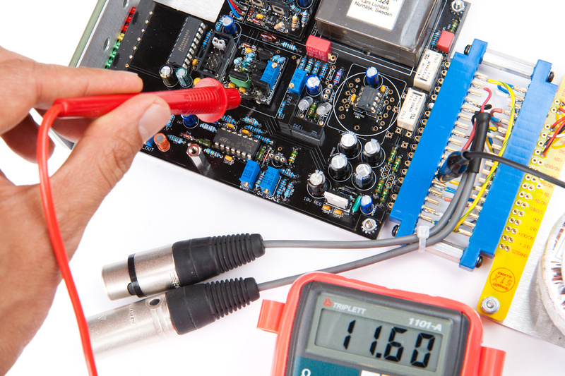
And, here's my problem. Test procedures say with input and output pots closed, I should adjust the input amp's trim pot to read .3V - 1V with a volt meter between the amps output and ground. At the end of the trim pot's adjustment range, I can only get it down to 11.6V which is wildly out of range.
Igor was out of town on vacation with limited network access and indicated he would get to my questions when he got back. In the meantime I attempted to build from my 2nd kit Igor's Cascode type input amp to test. I have awesome pictures, but unfortunately, I reversed D2 and D3 1N4148 like an idiot, so I got white smoke when I first powered it up. . . and I can't post the pictures because I don't want anyone repeating that adventure. Since I was looking right at the amp when I flipped the power on and shut it down in ~2 seconds, I'm hoping the damage is isolated to those parts.
Oh well, a trip to the electronics store tomorrow is in order. I also recorded all actual resistor values when building this one looking for discrepancies that could cause my voltage woes, and noticed that R6 and R9 (R6 6 being adjacent to the trimmer pot) have substitute values. . . 909K instead of 1M indicated on schematic. I'll pick up a pair of 1M resistors as well when I'm at the store and see if that gets me closer to where I need to be. Guess that's a 9.1% difference though. Probably insignificant but that's the only quirk I found.
Once more the Hakko 808 is saving my butt. Pulling out D2 and D3 on a built PCB would have been tough without it.
progress and problems today. . .
First, I needed to repair the 2nd Igor Cascode-type input amp that I smoked last night. Luckily, I have an electronics store local that actually has parts in stock. Hakko 808 to the rescue.
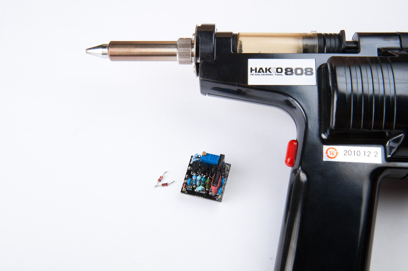
Since I had my de-soldering tool handy, I decided to replace the 901K R6 and R9 resistors on the 1st (mis-behaving) amp to see if that resolves my problems with it.
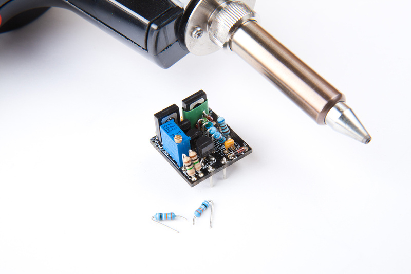
The bad news is the 1st input amp is still not showing the correct output voltage. It is now ~16 volts with the trim pot bottomed out. The good news is, the 2nd unit is working within spec.
It's trim pot is also bottomed out, but it's reading within the .3V to 1V specified range.
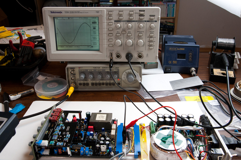
Next, I took out a whole bunch of tools I have no idea how to use.
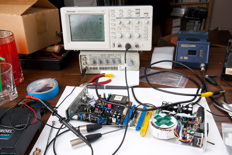
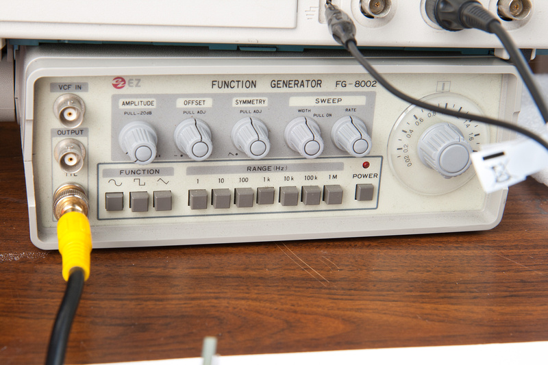
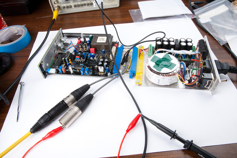
My friend let me borrow a function generator and a scope that didn't have a probe. . . the electronics store luckily had a probe at a not-to-astronomical price, so I was in business. So, these tools are now on semi-permanent loan since my friend seldom uses them anymore and they were in his storage unit.
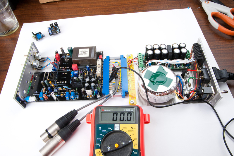
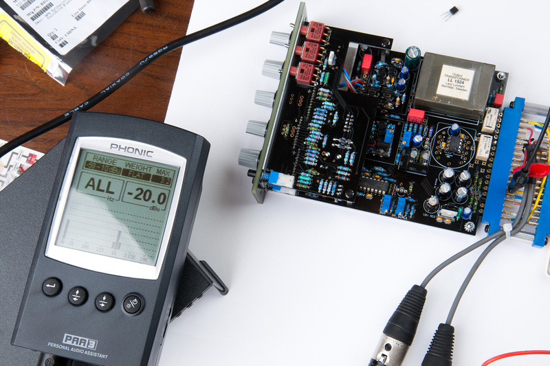
Since the F76 is balanced in and balanced out, I figured I should inject balanced signal, so I'm using my direct box which is of the IC opamp variety.
the setup on my table for starting to test.
ok. . . after pushing buttons like monkey on the scope, I think I finally figured out how to do some useful things with it. Please keep in mind, I've never used a scope in my life, so all this is very new to me.
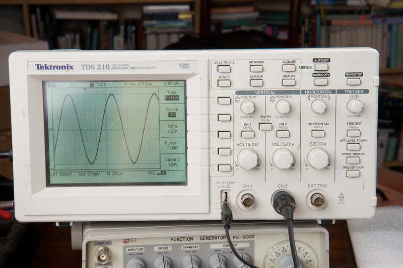
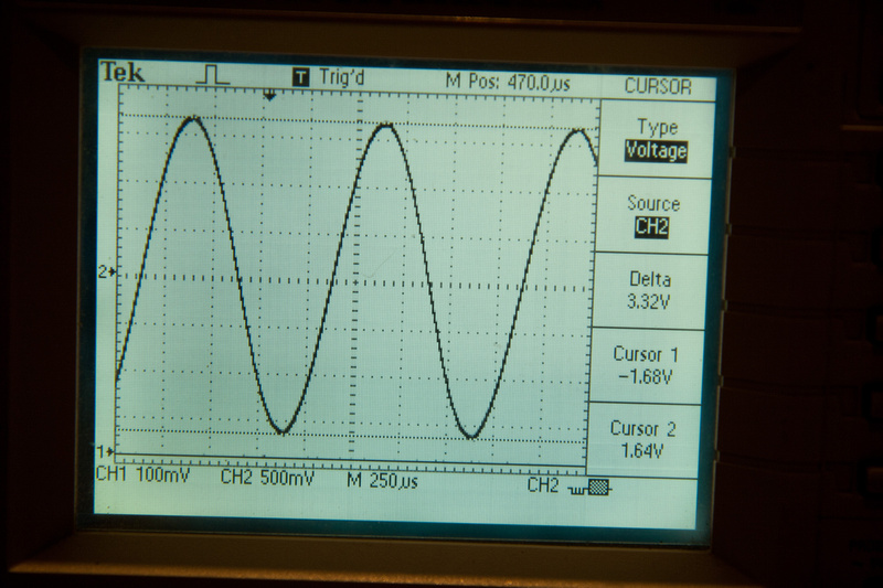
First test was to input a .01v RMS (-37.78 dBu) signal into the f76. Here I'm using a 1K sine.
And check output for ~37db undistorted gain. Here, I have 3.32v RMS (12.64 dBu) output w/ input and output pots both at maximum.
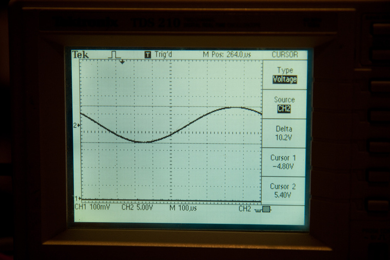
At this point, I discover another anomaly that I do not understand. My pin 3 and pin 2 outputs on the f76 are off by a large amount. Pin 3 output is 8.78db lower than pin2. I'm wondering if this indicates my output transformer is defective. It is evident in the photos that there is significant physical damage to the casing, but I assumed Andre had tested these before they shipped. The above reading is off of pin 3 (the low output one).
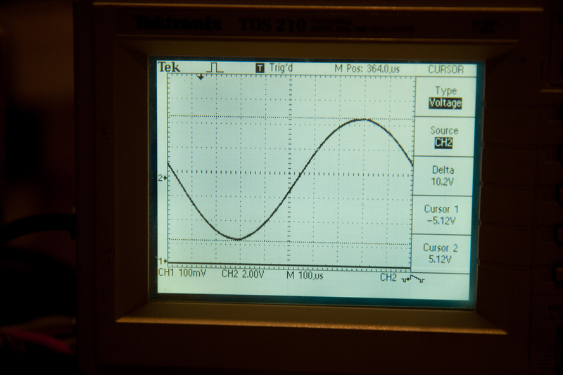
While keeping this issue in the back of my mind, I continue testing. I insert 1V RMS signal.
and max undistorted output on pin 3 is 10.2v (22.38 dBu) minimum of 24dB is Igor's spec.
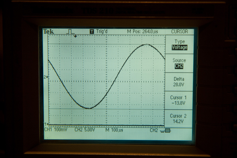
max undistorted output on pin 2 is 28v (31.16 dBu)
and, another view of the pin 3 output which is low.
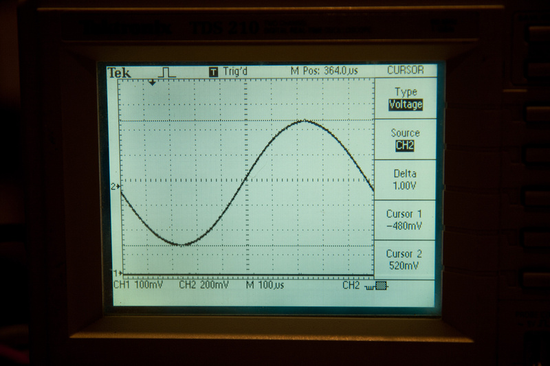
ok. . . problems aside, I move forward. I adjust input/output pots to output 1.23v RMS.
and adjust trim pot until yellow light is solid on the meter. The GR switch is in the "out" position.
At this point I had a couple of questions that needed answering.
1. What is my next step to diagnose the malfunctioning input amp that is giving me ~16v at output?
2. Do I have a defective output transformer that is giving me weak output on pin 3?
Concerning the malfunctioning IJ Cascode input amp is still a mystery to me. I went chasing around the schematic and PCB today with a patient and helpful friend on the phone trying to figure it out. Pulled the 50K trim pot. . . tested ok. . . re-installed it. Replaced Q2, T3. . . no change. . . Replaced C1, C3 mostly to make sure solders were all solid around the -24v area. Still no luck. This tiny amp was kicking my butt. Very frustrating. After some more swapping, I found the problem to be a faulty BD139 on Q1. Once replaced, the opamp trimmed out to spec.
Jeff from CAPI helped with my second question. It's more of a common knowledge answer that I simply was unaware of. Many output transformers do not have a ground reference, so they are floating ground. The + and - side of output will not necessarily reference to ground equally so the offset I am seeing on the scope is normal. I decided to calibrate 0 dB with a sound meter w/ a balanced input, and when I connected a load, the + and - sides evened up significantly on the scope. The output transformer is fine. Verified by pulling the output transformer and replacing it w/ same behaviors.
ok. . . one more push to finish up this build.
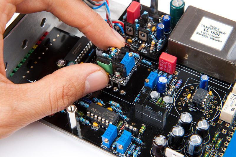
Please note, this step is pre-mature, so I will have to take out the audio and GR FETs for a calibration in the following steps, but this is when I put them in.
Audio FET here:
Gain Reduction FET here:
Note these are matched pairs provided in the kits and they are different than original spec FETs so these insert reverse direction from the markings on the PCB.
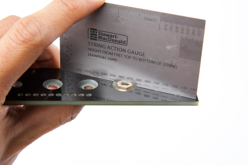
Next, I address a mechanical fit issue I noticed when rough assembling the module.
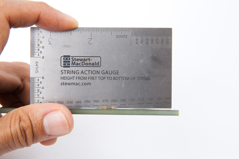
This nut is too thick to seat fully into the recess provided in the front panel, so we will have to thin it a bit.

Some 220 grit sandpaper does the trick.
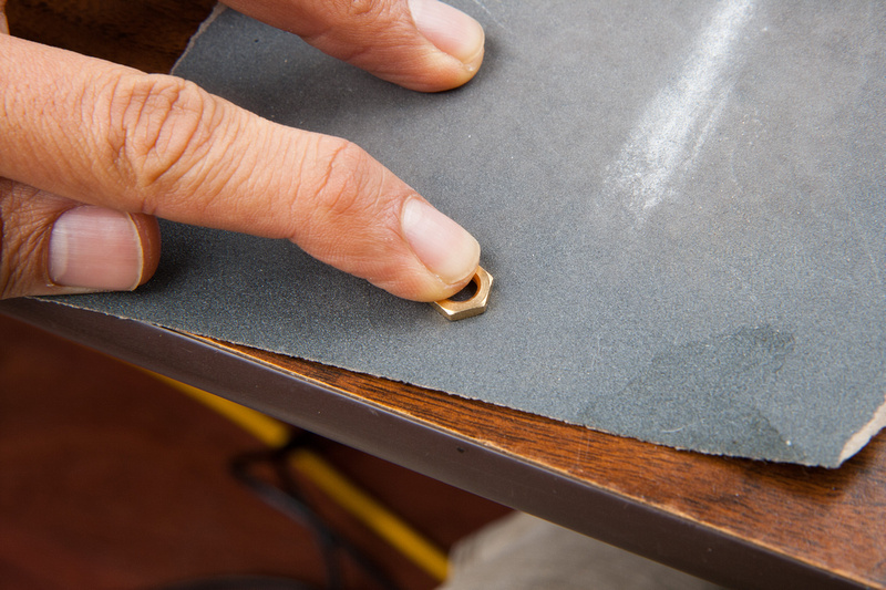
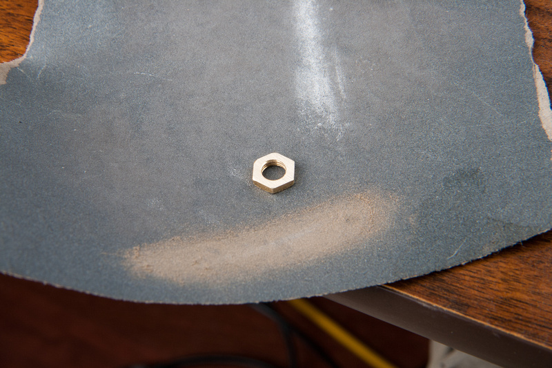
Fits now.
Next, I take out my jumper, attach the attack/ratio board, and assemble the whole mess again.
The front panel needed a bit more persuasion for everything to align, so I filed a bit on a few of the holes.
Voila!
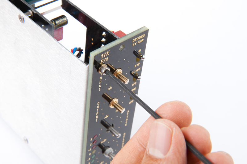
Next, I need to take care of these long pots.
So, I use a straight edge and mark my cut location.
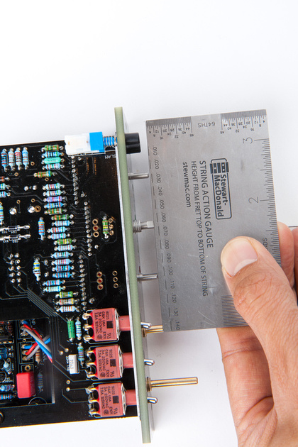
And cut with a cut-off wheel on a dremel.
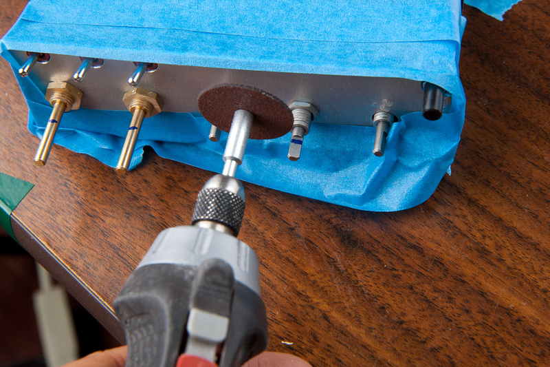
Voila! Look at that precision. . . it's almost like they were cut with a laser beam.
This hex screw secures the front panel to the L-bracket. There are 2 of them.
Next, I assemble knobs.
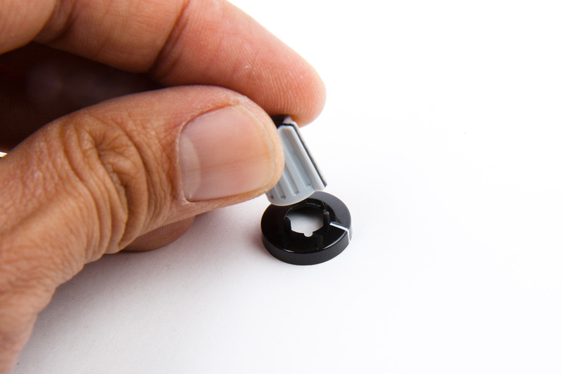
And secure them to the pots and grayhill swithes.
Now, I need to remove my GR and Audio fets and inject -20dB signal. Input pot set to max, adjust output pot to 0dB or 1.23v output.
Then, I re-install the audio and GR FETS and adjust bias for -1dB.
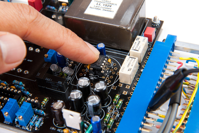
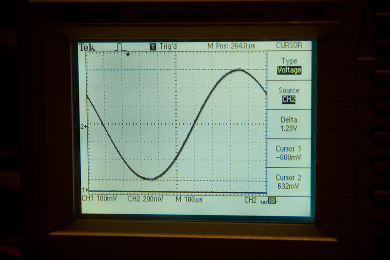
Next, I adjust the Dist trim pot. . . I read the instructions and am not quite sure I understand the adjustment procedure, but I put the output on the scope, increased the output until I saw distortion on the sine wave, and twisted the adjustment pot. So, it shifts the distortion more towards the top or bottom of the waveform. I adjusted until it was even top and bottom which should give me the greatest gain before distortion. I twisted the output pot back and forth from clean to distortion and toyed with it until the top and the bottom of the waveform flatten out at the exact same time.
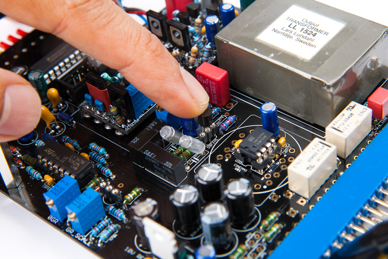
Next, I unplug input signal, put in GR mode and adjust 0GR trim pot for yellow LED to just light.
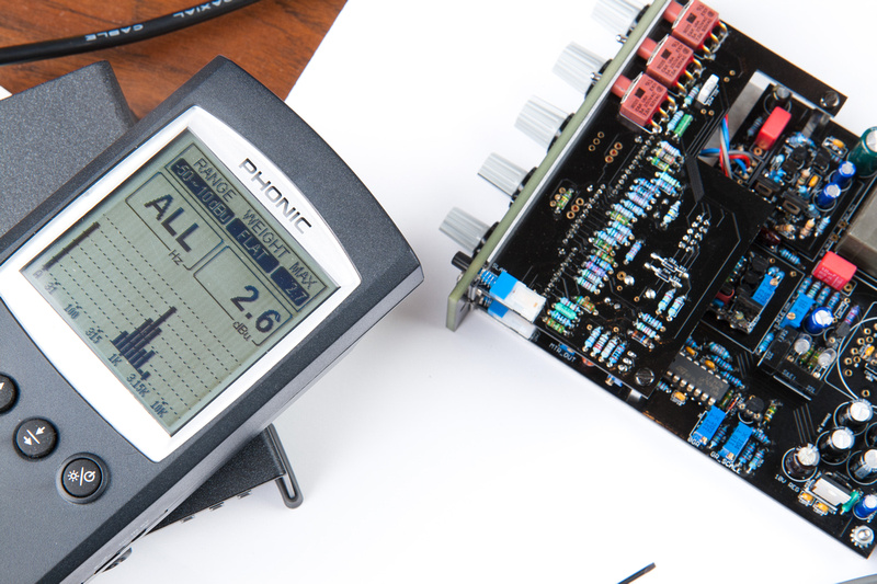
Then, I feet 0dB into the input, set ratio to 4:1 . . . and flip back and forth between OFF and 4:1 ratio. I adjust the input pot until I find the point where the difference between 4:1 ratio and OFF position is 10dB.
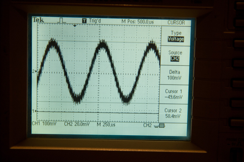
Here's my reading at 4:1 ratio.
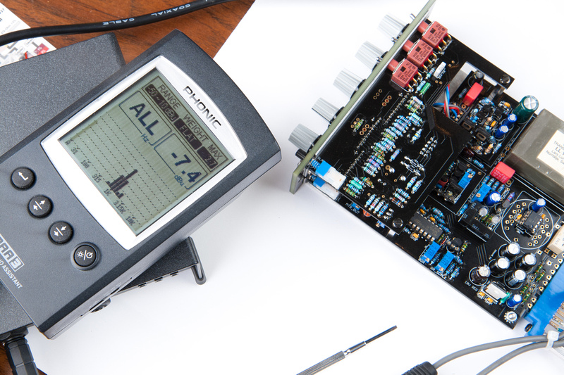
And my reading at OFF ratio.
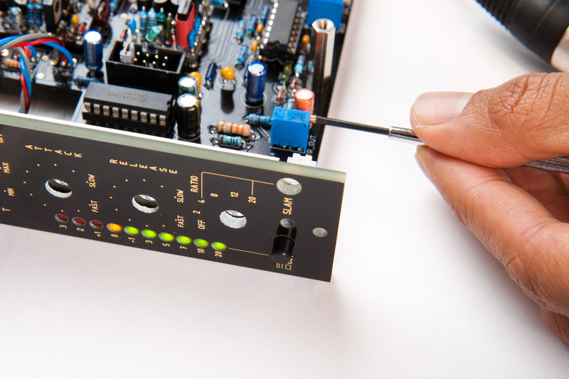
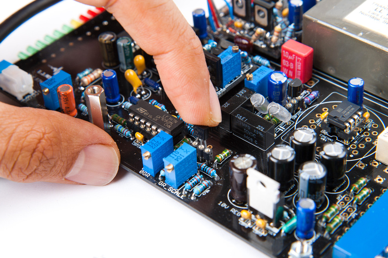
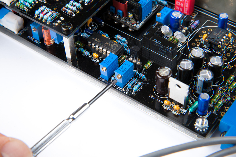
At this point, I return the ratio knob to 4:1 and adjust the GR scale trim pot until the meter reads -10
At this point, the unit is calibrated and ready to run. Humans Win!
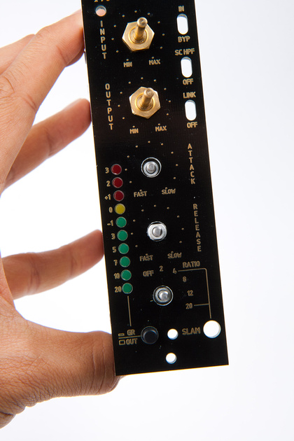
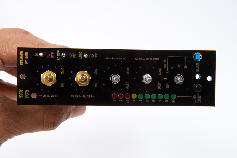
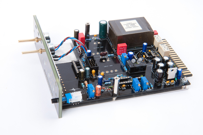
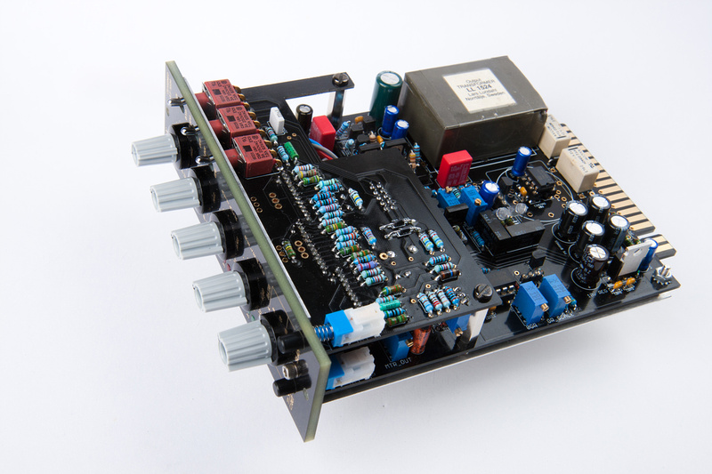
The only remaining step is to put the caps on the knobs and take pretty pictures of the finished product.
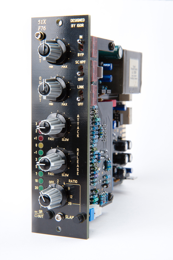
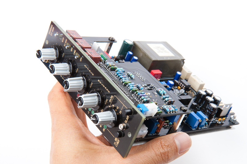
Well, there it is. I learned a lot from this project. It was the 1st time I used a scope. I was trying to figure out why the math all didn't work until I figure out unity is 4dB not 0dB for this equipment. I learned a bit about output transformers and floating ground. And I learned hot to use my Hakko 808 desoldering tool a lot better.
Well, I hope this gives everyone a getter look at the F76 project. Most of the calibration steps can be done with a volt meter or plugged into a DAW. One step (dist adjustment) is best done with scope. I chose to use the scope for many of the calibration steps because it's a new thing for me to learn to use.
I'd say this project mechanically is not the simplest and there are a few mechanical tolerance oddities and more general futzing than some other kits, but in the end, I think the final product if carefully assembled polishes out really nicely. The internal component arrangement is slick, and the feature set is awesome. 2:1 ratio and true relay bypass is awesome. The metering is a treat to use. I really like the way Igor set up the physical metering and programming to drive the meters. Very intuitive in use. I can't wait to get this module into the studio and hear it in a good listening environment.
Nicely done! Whats that igs op amp mod?
ReplyDelete