In my opinion, the all discrete Classic Audio VP26 preamp delivers the highest cost to performance value among all of the kits currently available. It also happens to be one of the easiest builds for a first time audio DIY project and was my entry point into the world of audio DIY. In this post, I will try to show the entire build step by step.
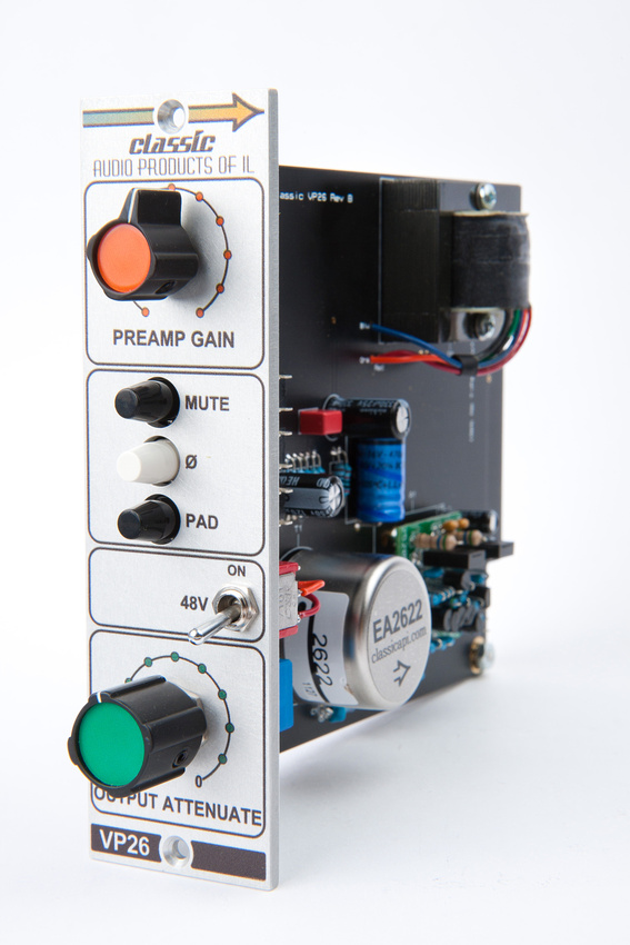
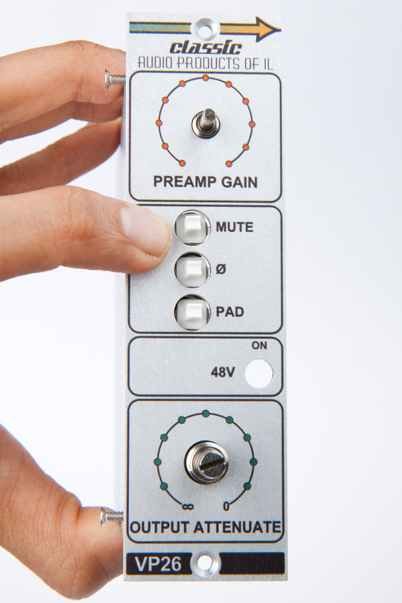
The VP26 preamp is faithful recreation of the legendary preamp circuit found in mid-late 70's API recording consoles and conforms to the now popular 500 series card slot specifications. A VPR compliant rack of some kind is necessary to run this preamp. The 11 space GroupDIY 51X rack kit and its corresponding power supply kit is an excellent, highest-quality option distributed in the US through Jeff Steiger of Classic Audio Products. The popular 6 space API lunchbox is another cost-effective option. A lunchbox loaded with 6 of these VP26 preamps built with care would make a formidable drum tracking tool and would be a welcome guest or permanent fixture in any recording studio.
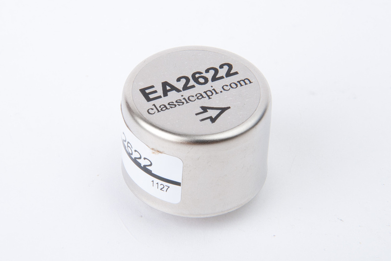
The VP26 now comes in silver face and black face options. It also comes with either a constantly variable gain potentiometer or stepped gain switch options. This post will show the variable gain version with the silver faceplate. A 2520 type discrete opamp is also required for this kit and one needs to be selected upon purchase. My "go-to" opamp is Gary Barnet's GAR2520 opamp kit for a scary-close approximation of the vintage Huntington API opamp that is no longer made. The opamp kit requires a very steady hand and good soldering iron to build and carries with it a much higher chance for newbie build errors than the VP26 preamp kit. For the first time builder, I recommend purchasing a pre-assembled/tested opamp or at minimum a few spare opamp kits just in case one of the your first opamp build attempts fails.
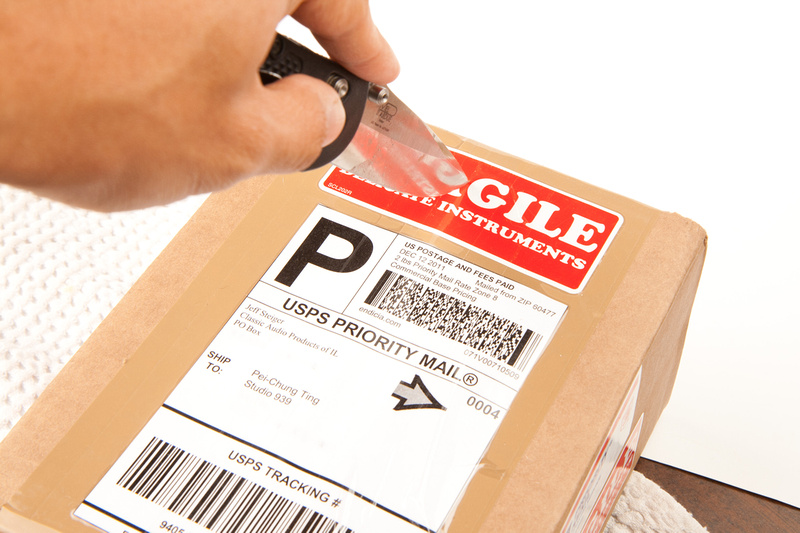
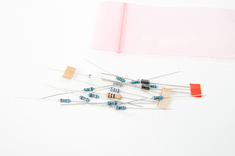
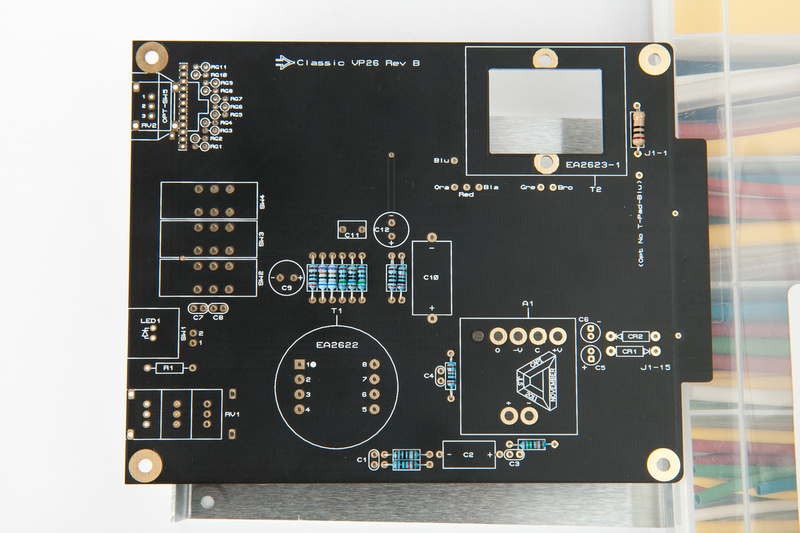
That being said, let's get started and see what's in the box.
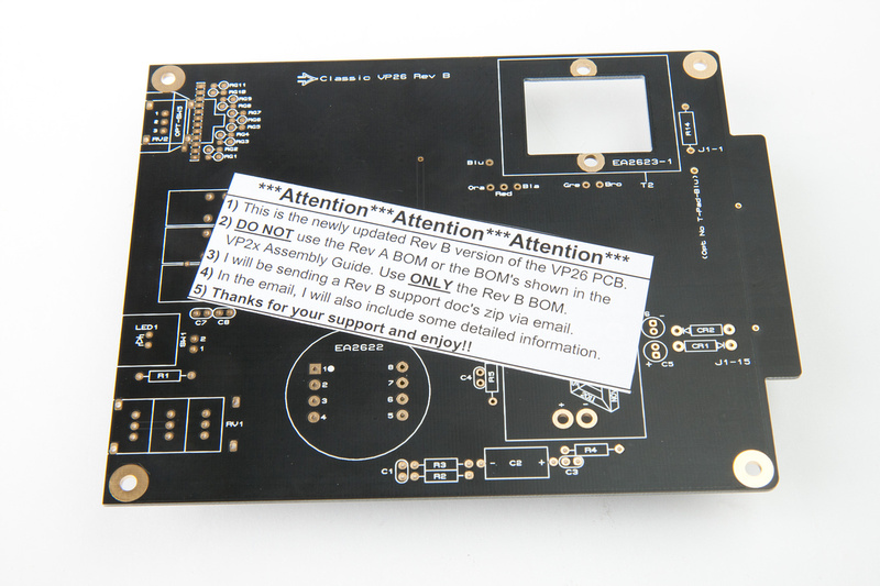
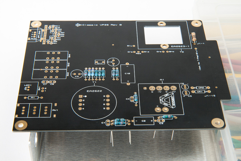
First, notice the new Rev. B printed circuit board and a note to use the proper bill of materials for the Rev. B board.
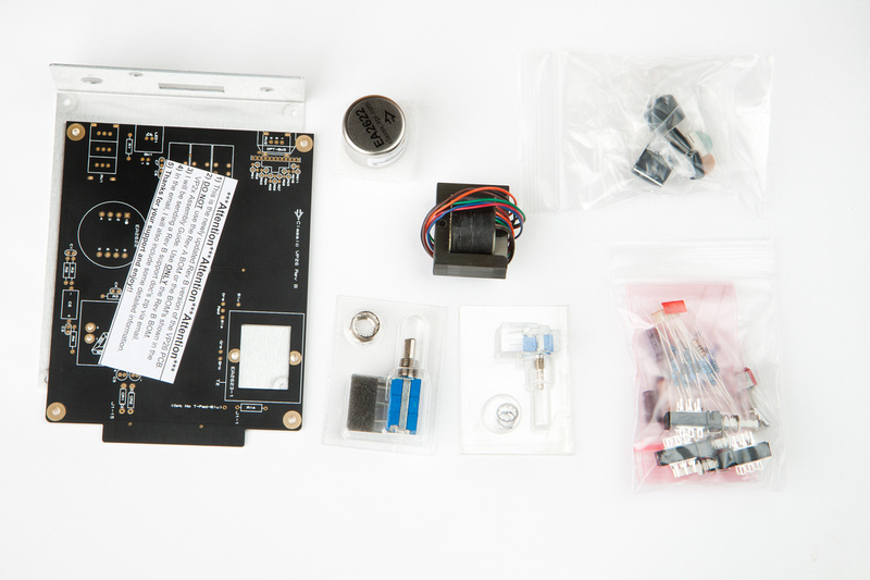
And here are the rest of the kit's components (note: front faceplate missing from photo).
I decided to follow the general format of the VP26 assembly manual and start with the resistors. . .
Well, on second thought, I decided to just go ahead and sort all of the components according to the new REV. B BOM because there are not that many components in this fine circuit.
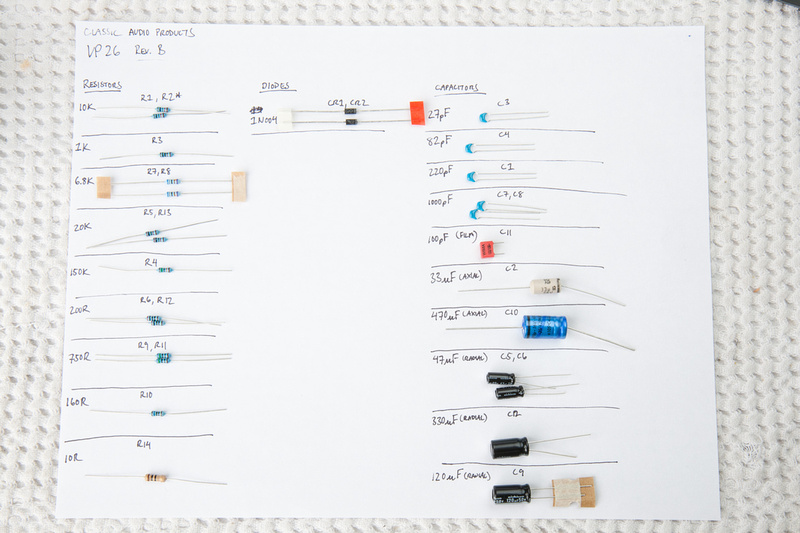
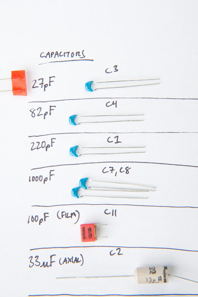
The markings on the ceramic capacitors are very small. Be careful when sorting these and verify that they have all been properly identified.
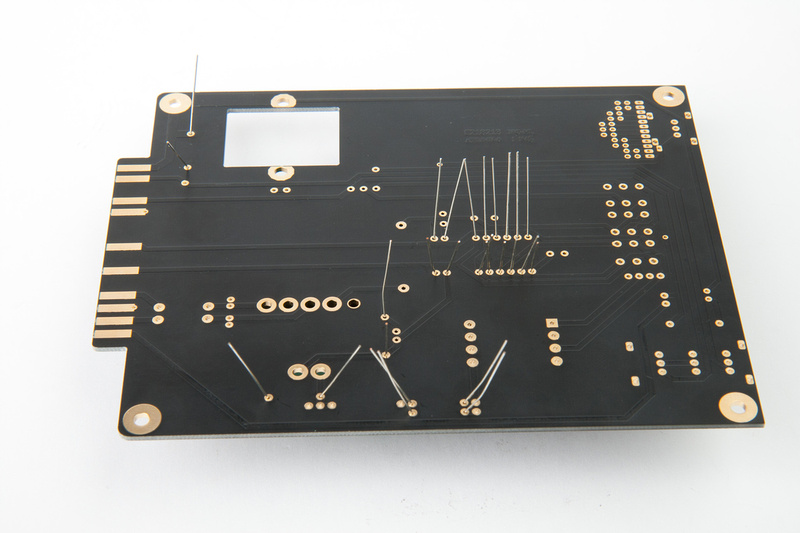
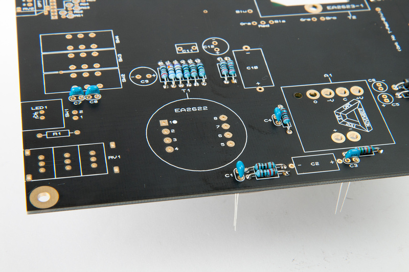
Next, elevate the PCB on something and place the resistors. I simply use the L-bracket included in the kit along with random found objects near my work area.
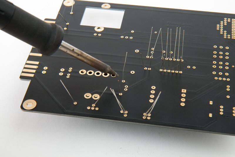
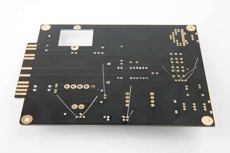
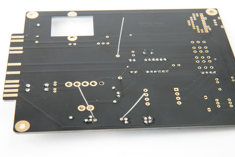
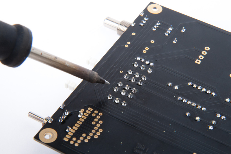
The recommended assembly method now is to bend the leads and solder from the back side. . .
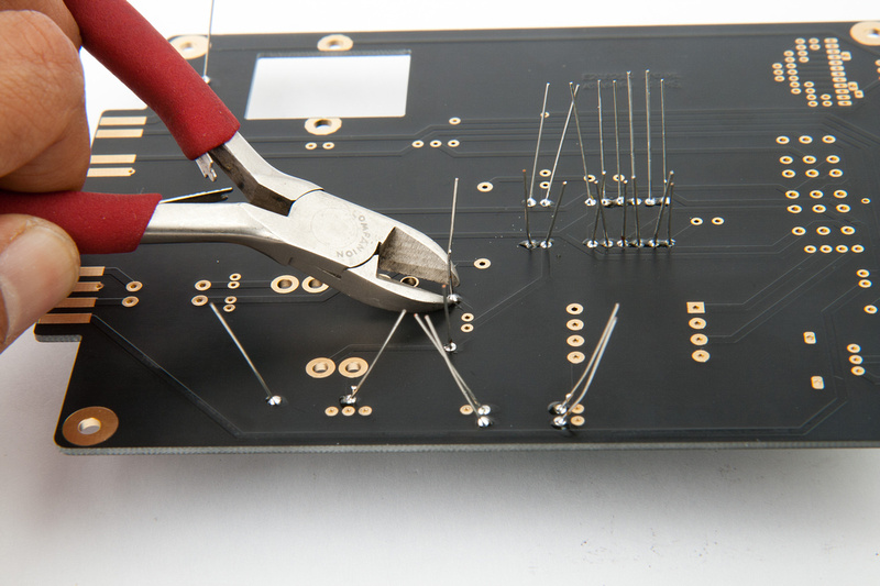
After soldering, trim the excess leads close to the PCB.
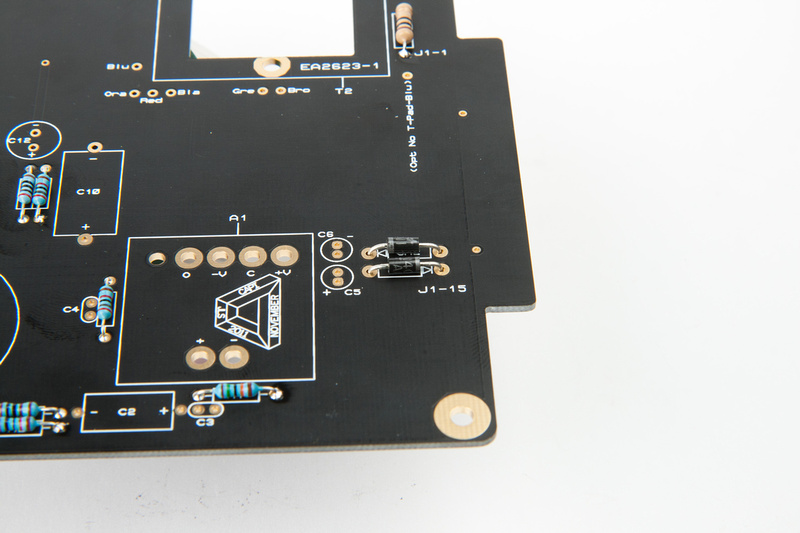
Next, I install the 2 diodes in the same manner making sure to place them in the correct polarity. The end of the diode with the solid line corresponds to the arrow screen printed on the PCB.
Next, install the small ceramic capacitors.
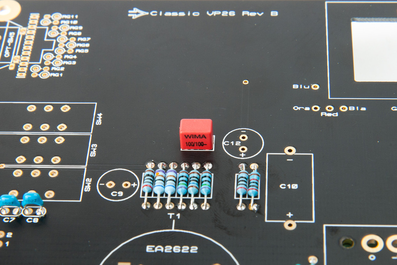
. . .and then the WIMA film capacitor.
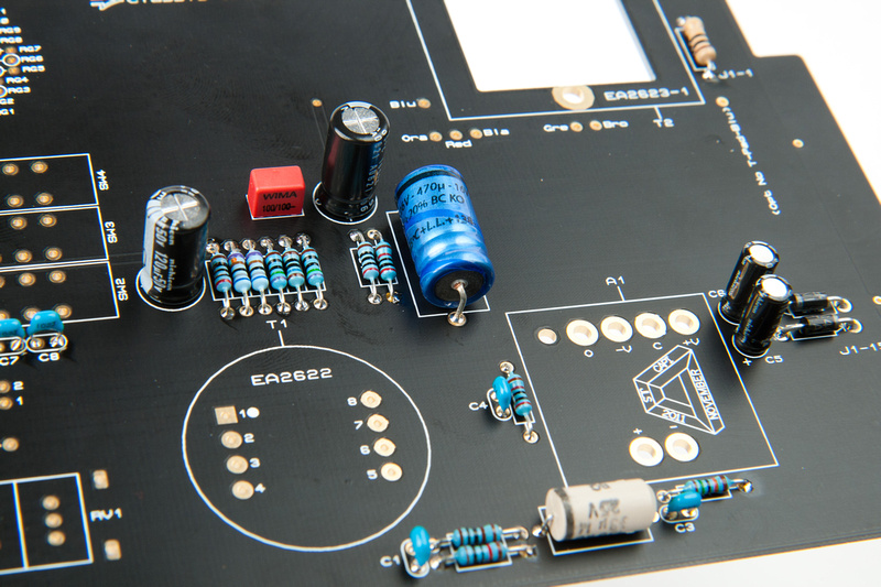
Axial capacitors go in next. Polarity is important on these. Please double check and make sure they are facing the right way. Solid line indicates "-" side of the capacitor.
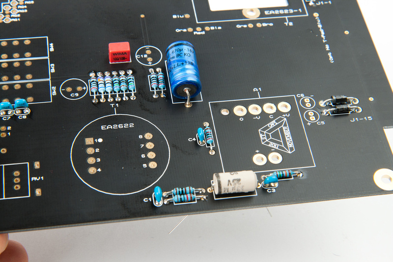
Then the radial capacitors go in. . . again, these have polarity. Make sure you insert the longer of the legs into the "+" marked hole and the solid line on the body of the capacitor corresponds to the "-" terminal.
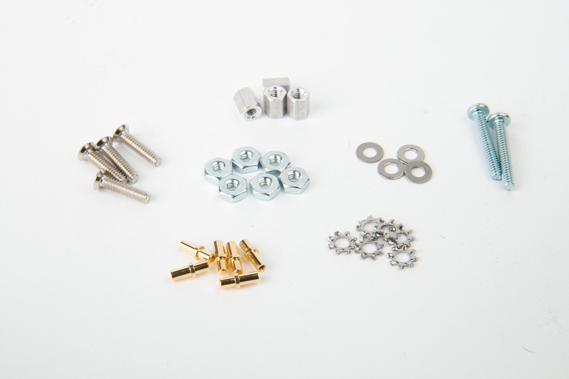
Next, sort the hardware.
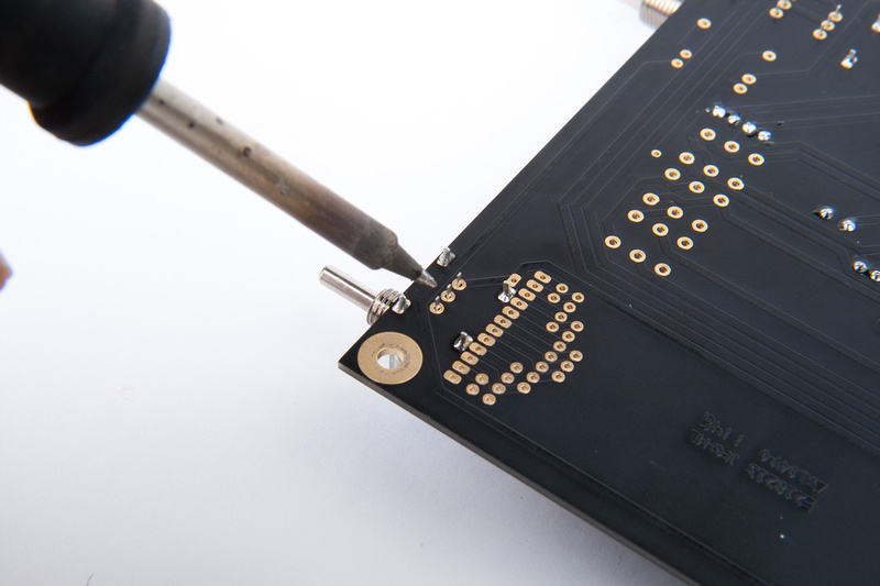
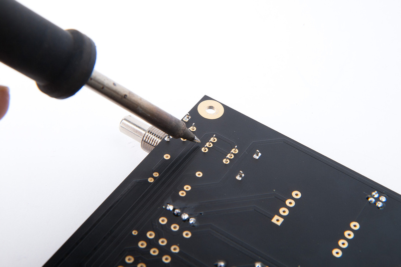
Locate the Milmax sockets and place them from the back side of the PCB.
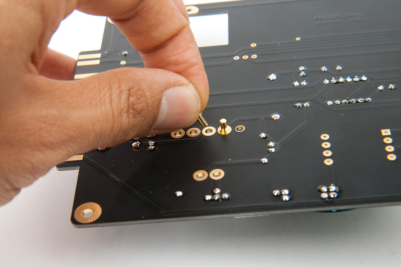
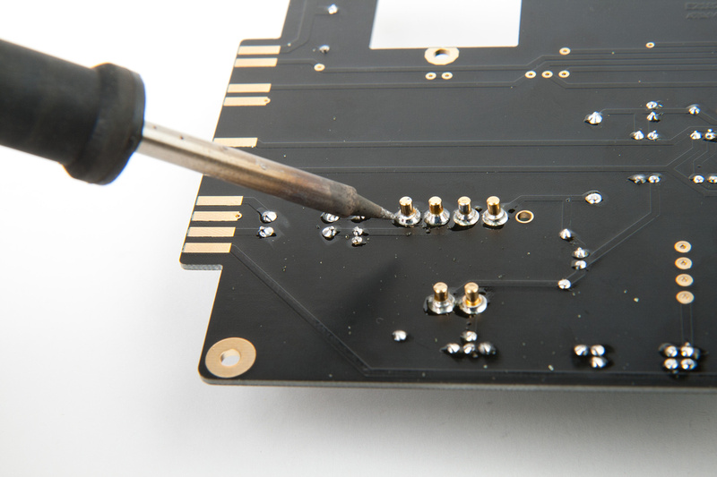
And solder from the back side.
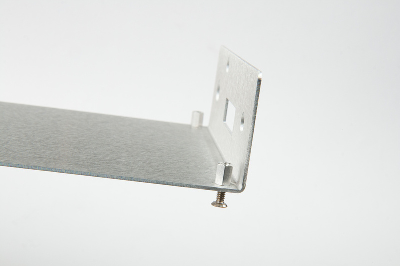
Next, install the screws and standoffs on the back side of the L-bracket to final torque.
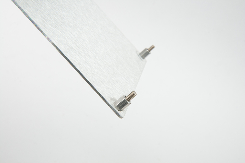
And for the front side of the L-bracket, we install the screws half way so we can slide the PCB and attached switches/pots over the standoff.
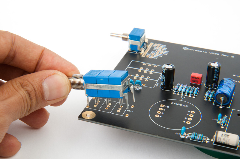
Next, we attach the gain pot, but remember NOT to solder yet! (Note: I am building the standard configuration here with a Bourns pot. . . there is an option for a stepped grayhill switch on the PCB that we will not utilize in this build).
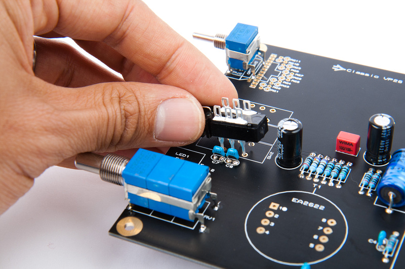
And, place the T-pad. . . again, DO NOT solder yet. You may need to bend some of the legs to straighten them in order to get the t-pad to fit onto the PCB.
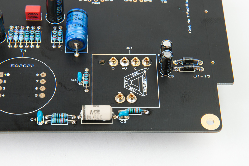
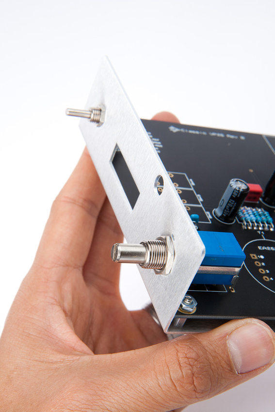
Next, assemble the main PCB to the L-bracket with the pot and T-pad loosely placed.
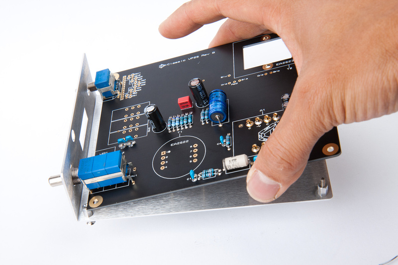
Align the pots to center on the L-bracket holes to the best of your ability.
Install the nuts to lock the pots into final position. . .
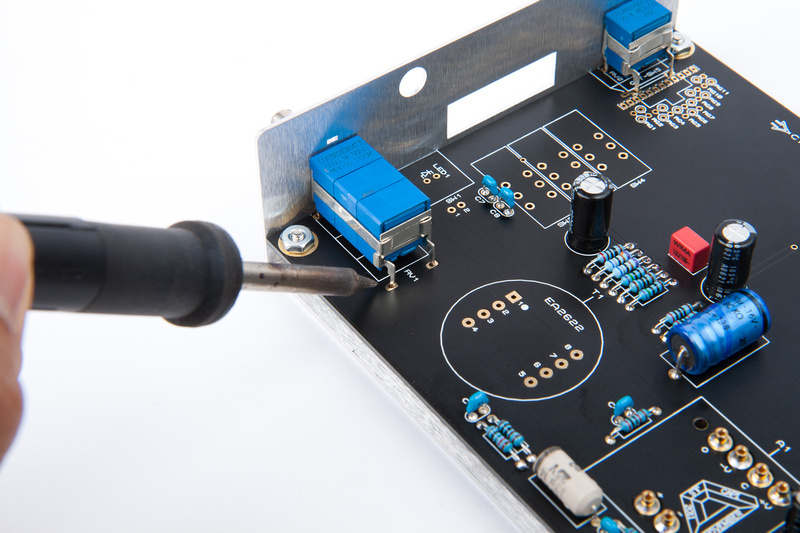
Now, with the t-pad and the gain pot secured in their final positions to the L-bracket, solder as many of the solder points as you can reach.
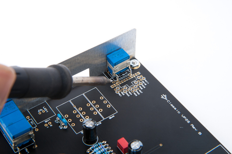
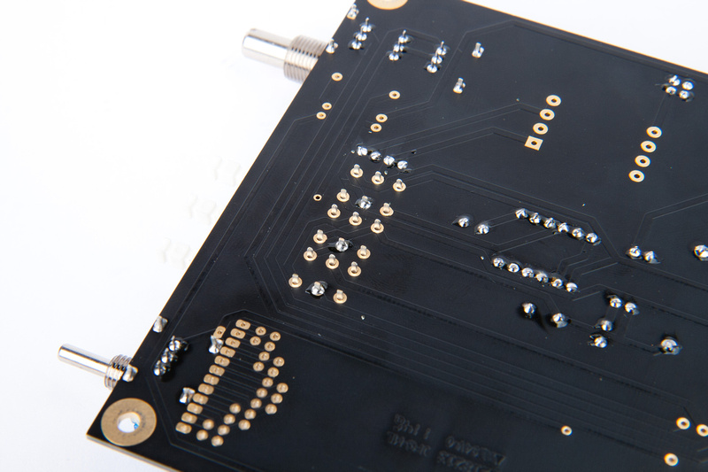
Next, disassemble the PCB and solder the remaining lugs from the back side.
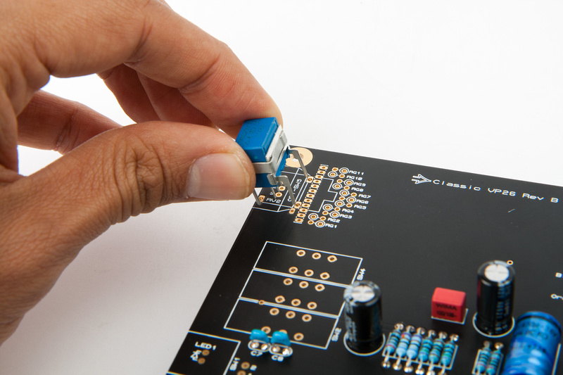
Next, place the 3 push-button switches pressing firmly to the PCB surface
I solder only 1 center lug on each switch.
Then, I re-assemble the PCB to the L-bracket and the front panel to check for optimal alignment of the 3 push-button switches. I slightly tweak the angle to optimize if necessary. Keep in mind there is still a little bit of adjustment possible on the front panel positioning, so I try to get this as close as possible, but still have some room to maneuver if necessary.
And, solder in the rest of the lugs. I jump around a lot to keep from overheating the switches during this operation.
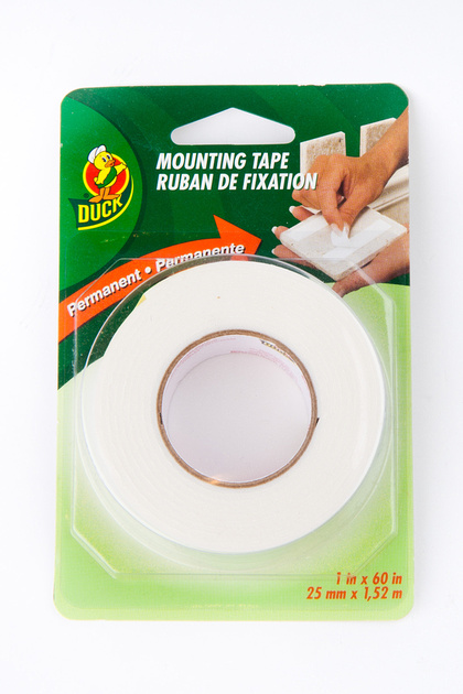
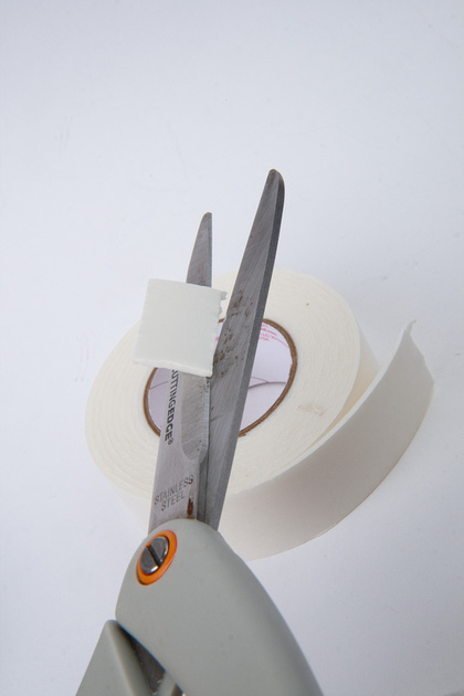
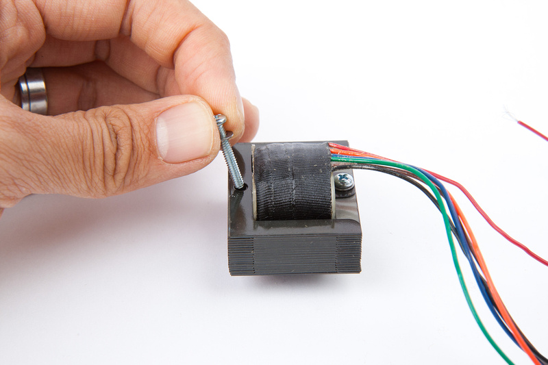
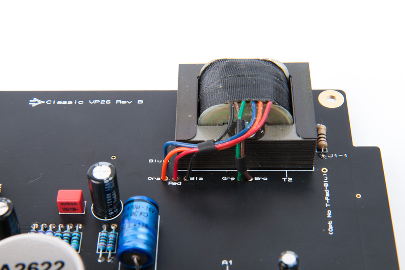
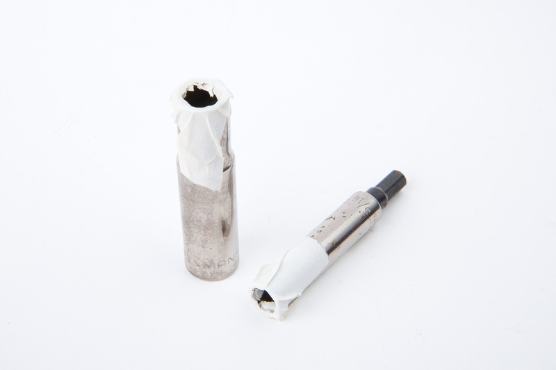
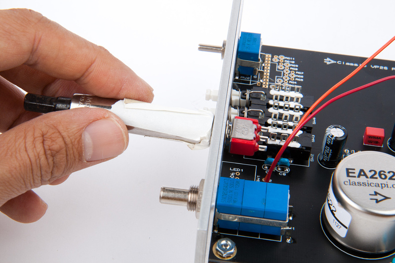
since the ground plane was moved to the front side, it's a little bit more critical in the rev. B to use some sort of insulating tape on the input transformer.
I purchased some double sided tape from Home Depot for this.
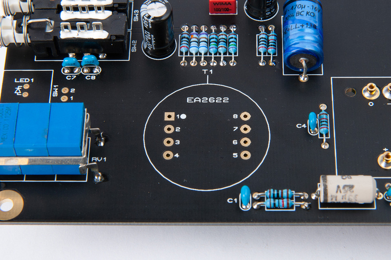
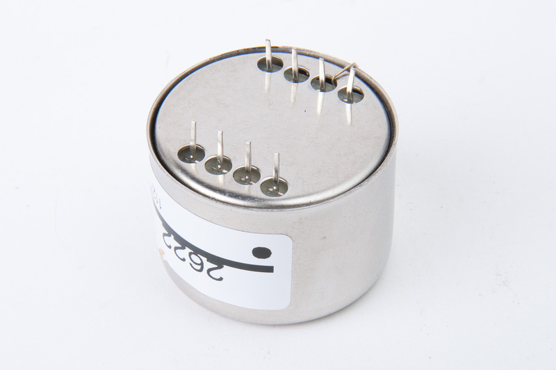
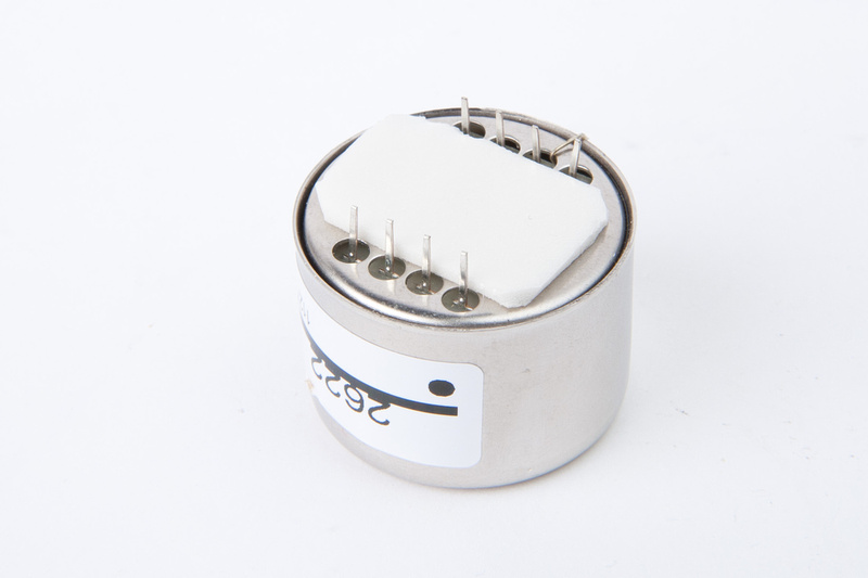
Note the position of pin 1 which is marked with a dot on the transformer's label sticker and clearly labeled on the PCB.
I cut a piece of double sided mounting tape
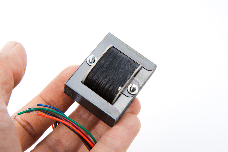
And apply to the bottom of the transformer
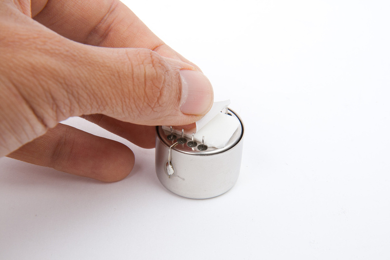
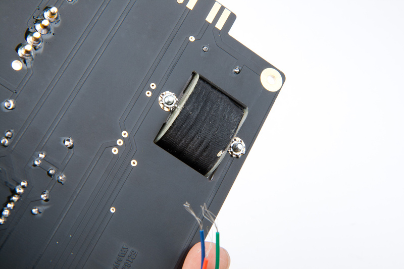
Next, place the transformer making sure to align pin 1.
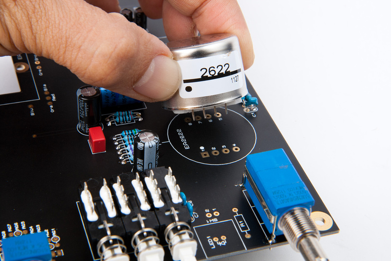
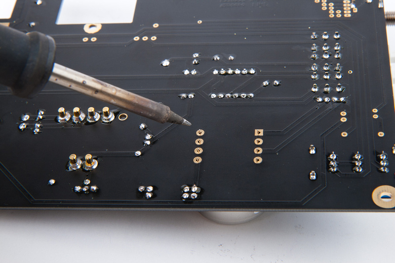
And solder from the back side.
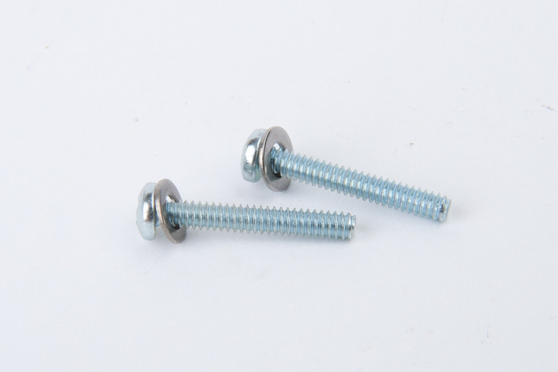
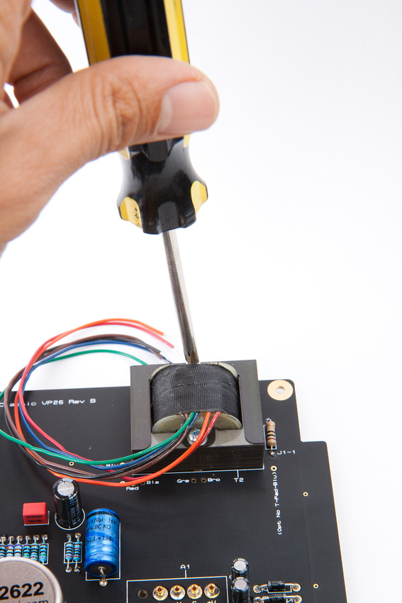
The output transformer is installed next. . . find screws and washers and put in this configuration.
Insert the screws into output transformer from the top side.
While holding the screws in position, flip the transformer over and put 2 more flat washers on under the transformer.
Position carefully on the PCB and place 2 lock washers.
Then, the nuts go on. . . I found it easier to tighten from the screw side while holding the nuts in place.
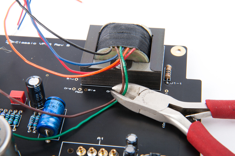
Carefully trim the output transformer wires to the correct length. . . it's easier to leave them longer than necessary and trim several times to get to the correct length than to trim them all at once and too short. . . if that happens, hilarity would ensue.
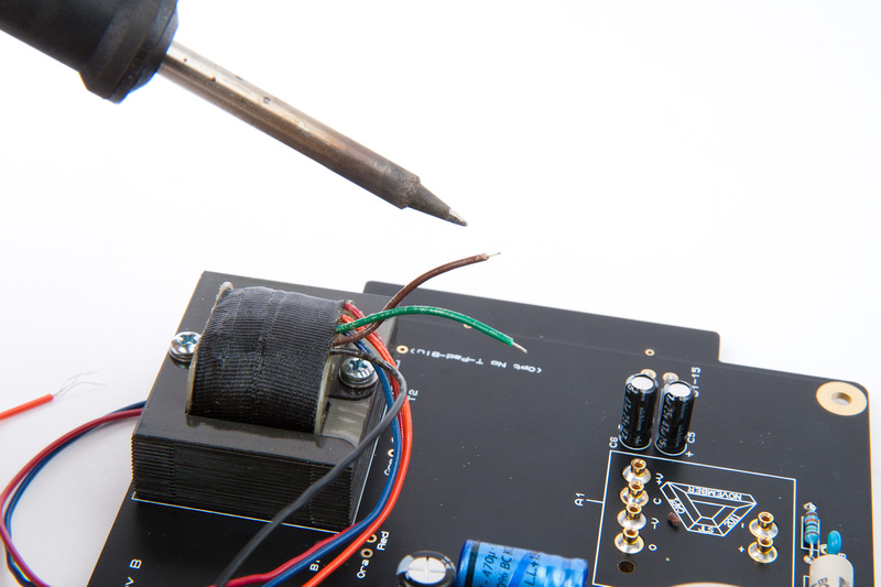
Once length is determined, strip back about 1/8" and tin the tips before inserting into the color-marked hole and soldering from the back side.
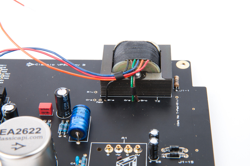
I used a couple short pieces of shrink tubing to clean things up a bit.

Repeat for all the other output transformer leads. Lengths will vary.
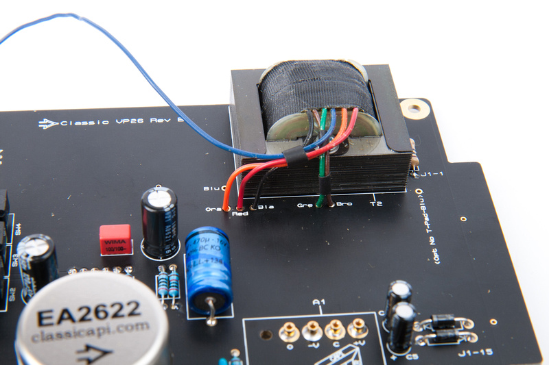
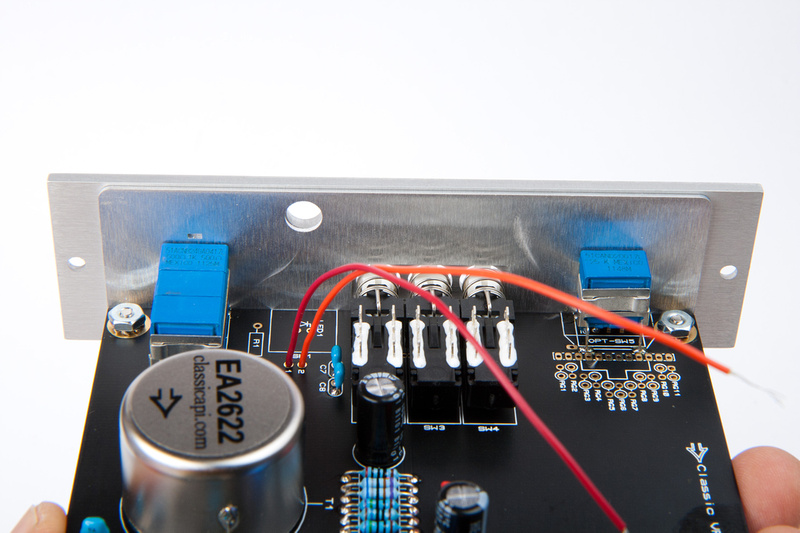
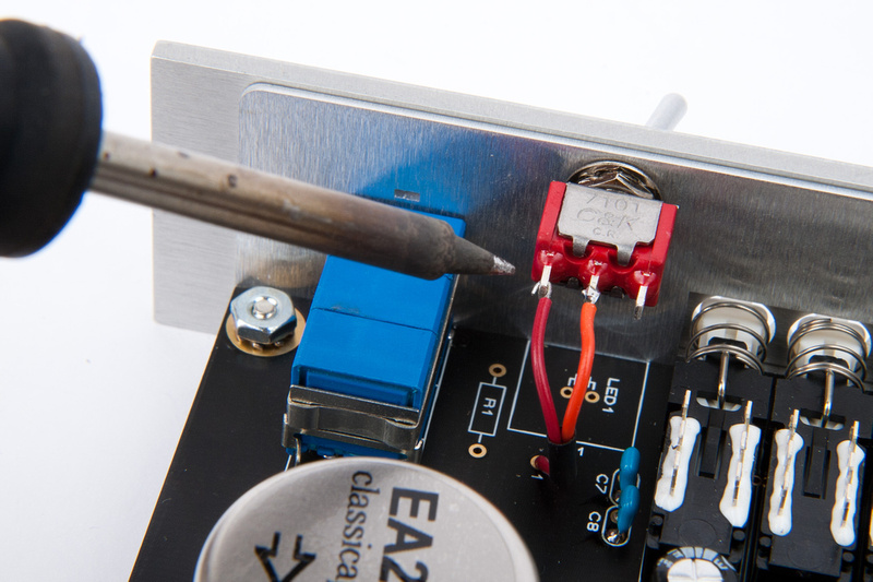
Next, grab the excess red and orange leads from the output transformer.
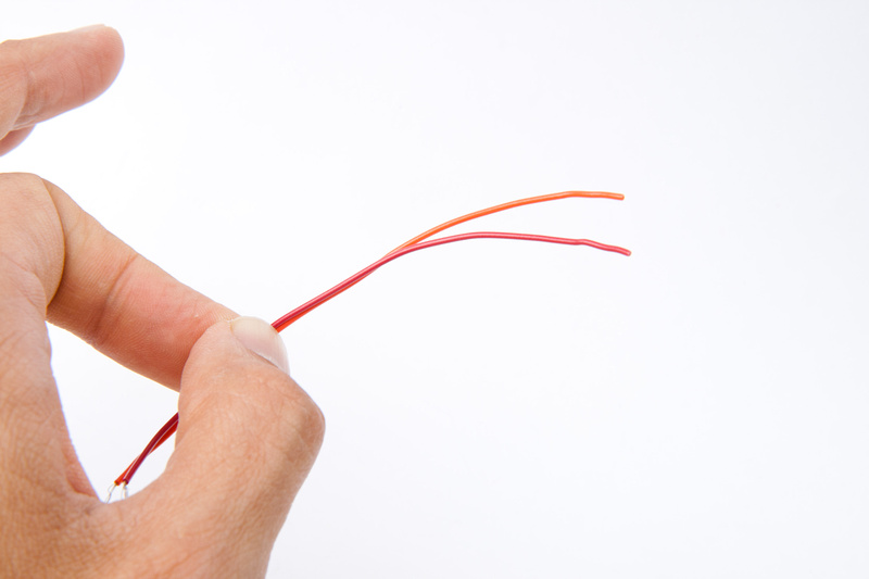
Strip back about 1/8" on the ends and tin them.
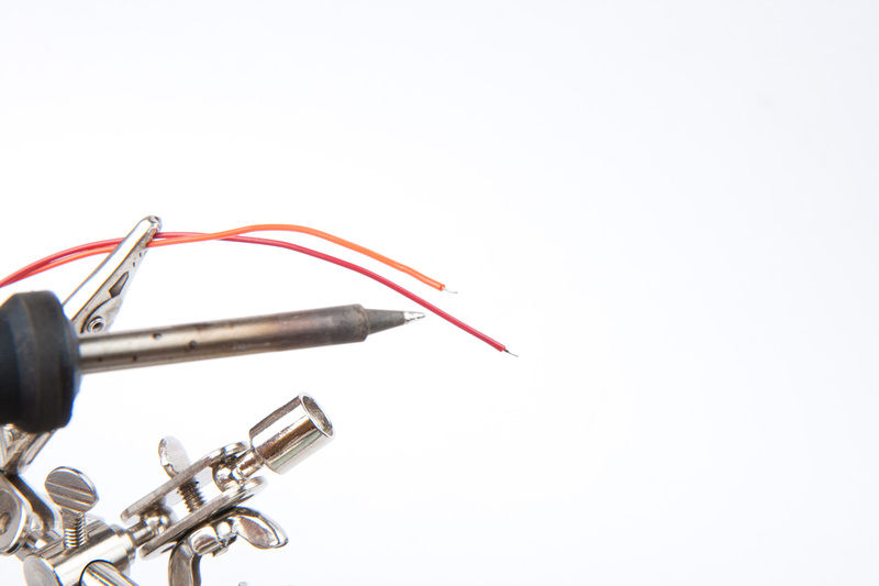
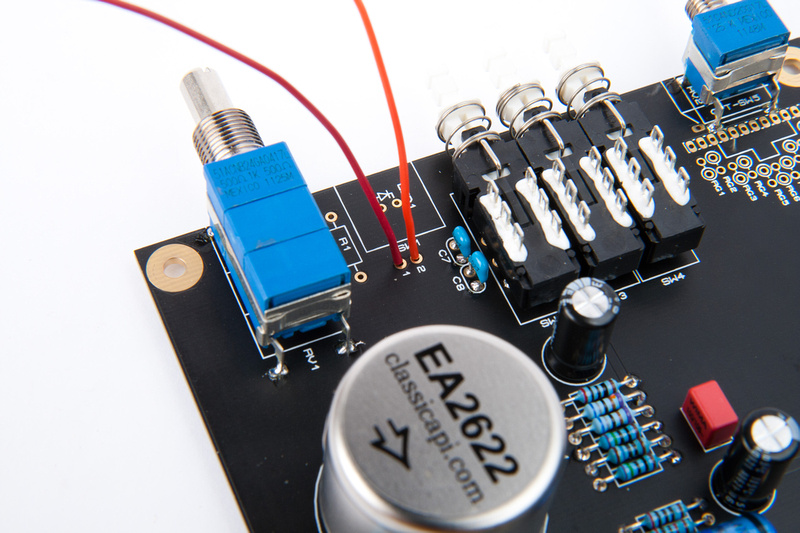
. . . and solder these leads into the holes labeled "1" and "2".
now, re-mount the PCB to the L-bracket hopefully for the final time.
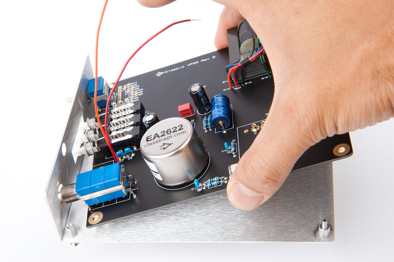
Use lock nuts this time to secure the PCB on the standoffs.
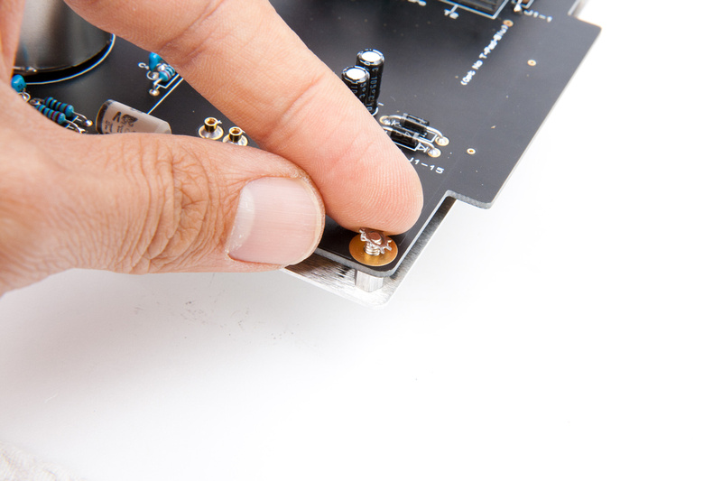
. . .and snug them down.
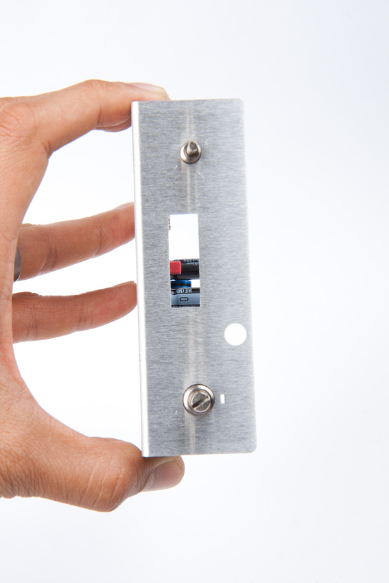
voila!
to protect the finish on the front panel, I used console tape on the sockets to tighten the nuts onto the knobs.
reference the top edge of the L-bracket and front panel to make things straight when tightening the nuts.
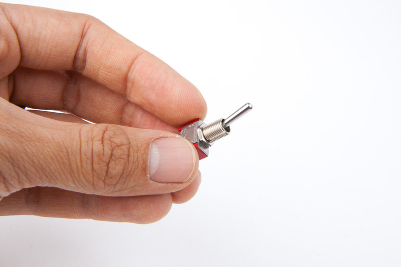
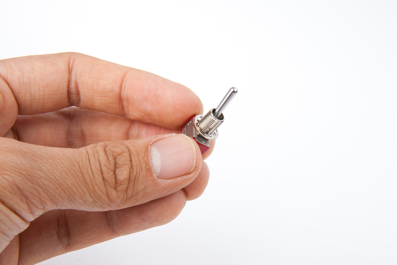
Next, locate the phantom power switch.
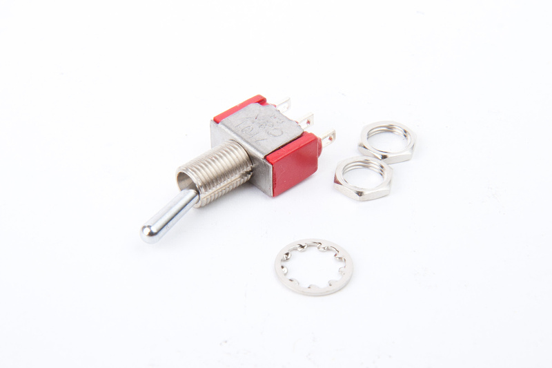
Thread one of the included nuts onto the switch. . .
Then, add the lock washer.
Position the switch onto the front panel.
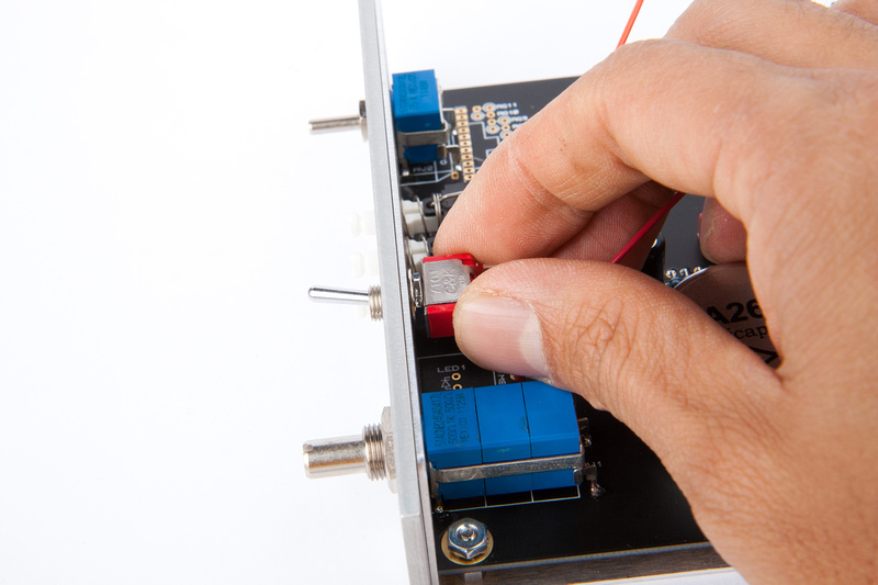
And secure the remaining nut from the front side being careful not to mar the front panel
Next, cut the red and yellow leads to length and solder to the phantom power switch.
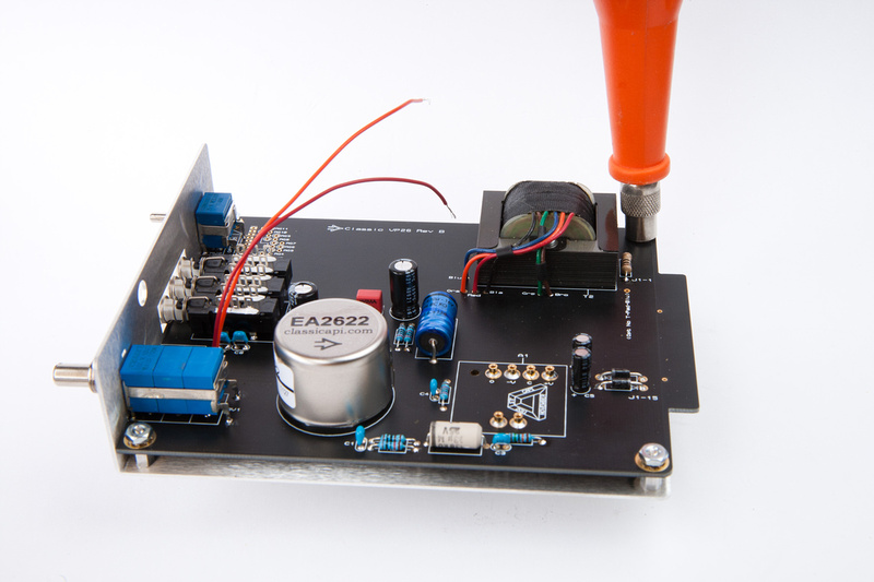
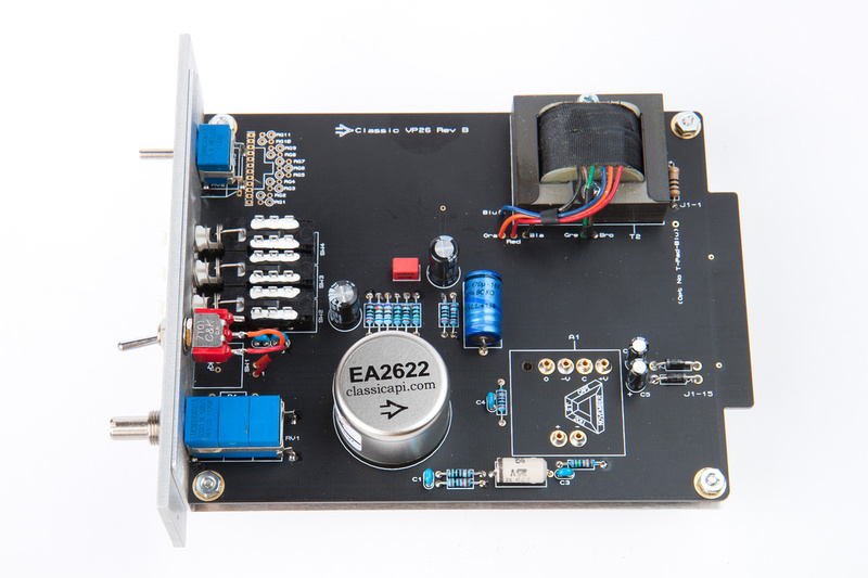
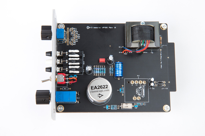
The preamp is now complete as far as the electronics go.
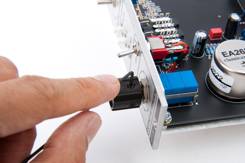
Next attach the knobs with the allen key set screws.
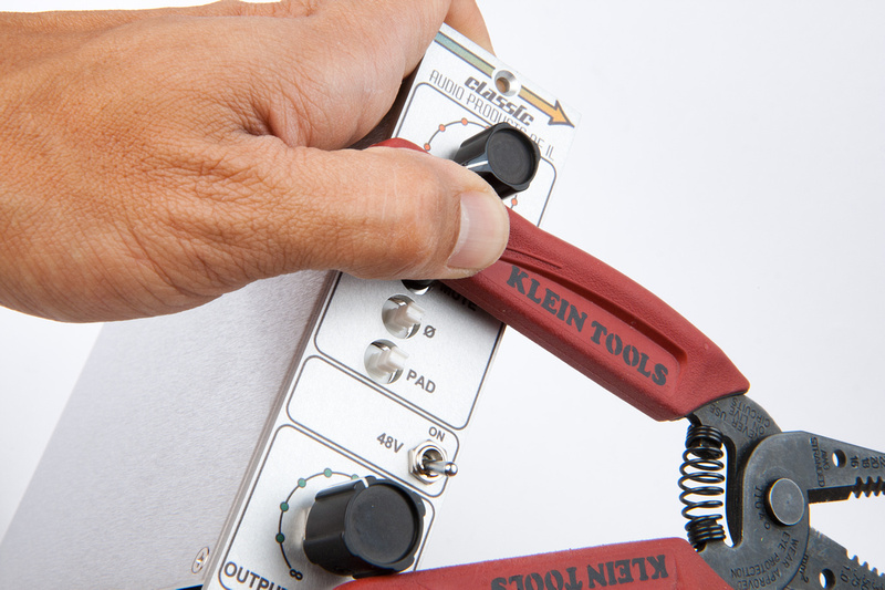
Locate the push-button caps
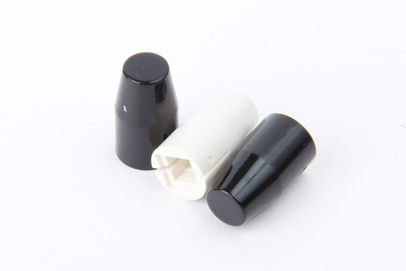
And press them on. . . a little force might be required here. I use the rubber, padded end of my wire strippers.
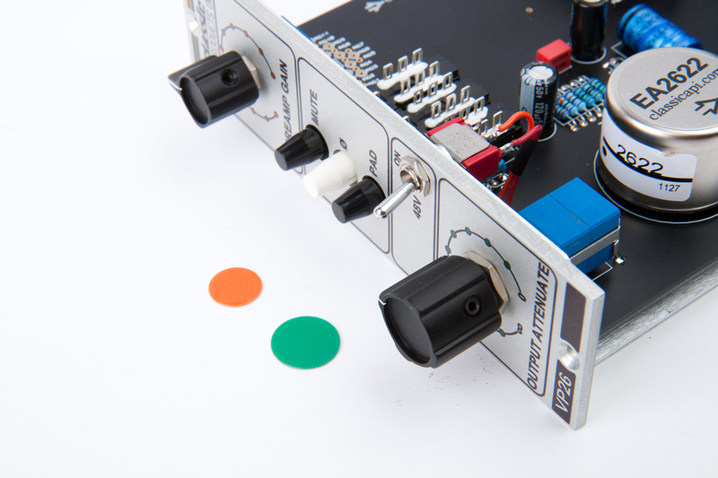
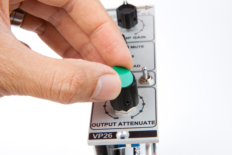
Next, apply the colored decals to the knob centers to finish up the cosmetics.
And the VP26 rev. B kit is complete.
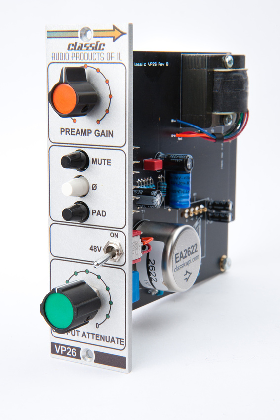
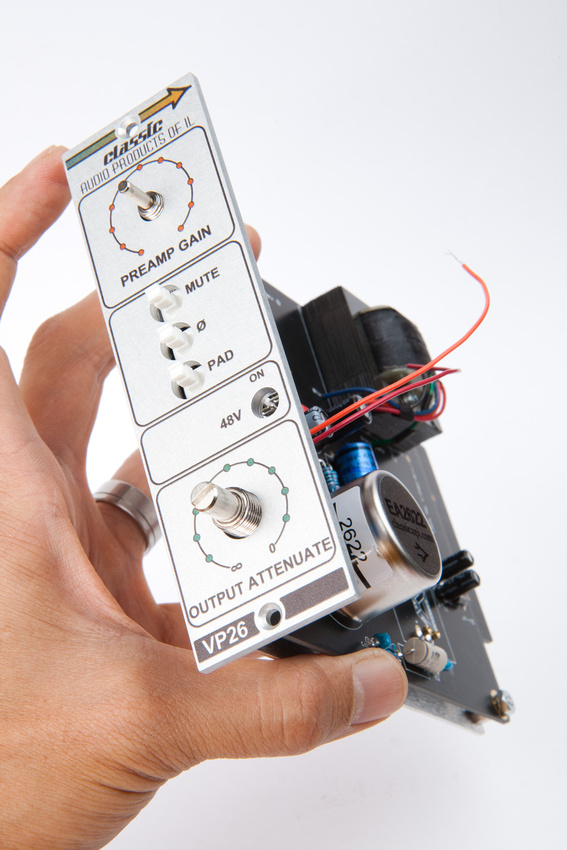
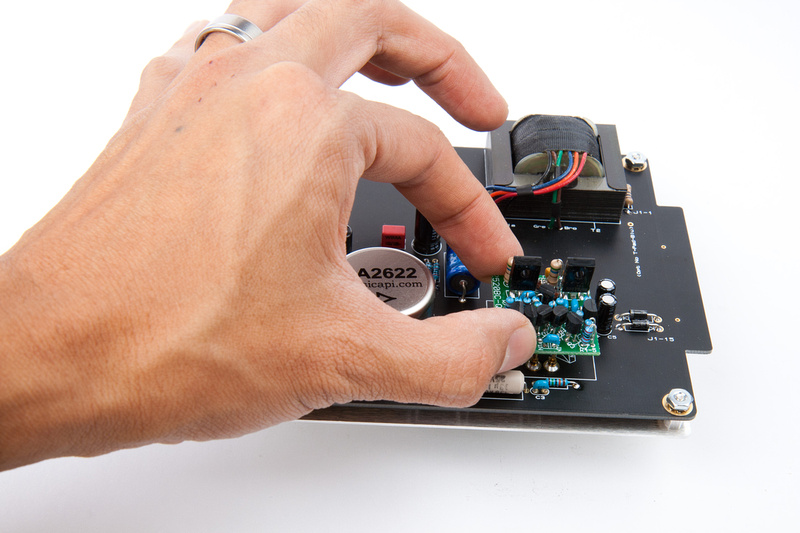
Follow the test procedures outlined in the original build manual, and install the opamp of your choice. Here I'm using one of Gary's Barnet's fine GAR2520's.
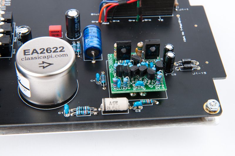
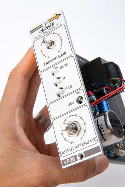
And, fully assembled.
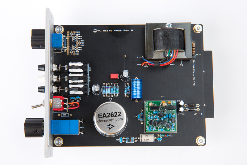
Humans win!
If all went well, the preamp should plug in and fire up right away. If all did not go well. . . uh. . . Jeff Steiger is one of the most responsive kit providers that I know and actively monitors the official support thread for this kit on the www.groupdiy.com forum.
This comment has been removed by the author.
ReplyDeleteAwesome ! Love U Dude ! Thanks =)
ReplyDeleteBrilliant!
ReplyDeleteI noticed you didn't install R1 but couldn't find a reason why. Is there a reason you didn't install R1?
ReplyDeleteExcellent post! Great Pictures -Thanks
ReplyDelete