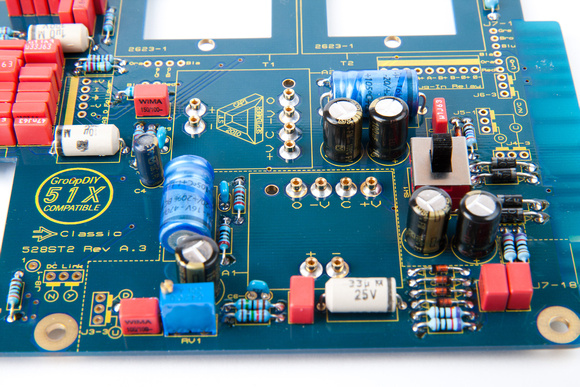
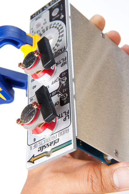
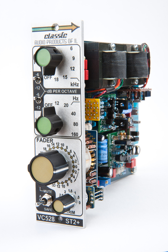
The VC528 is a unique 500 series or 51X module in that it is a "go-between" design. While it is common to find preamp circuits from a variety of vintage consoles in lunchbox form, this module re-creates the rest of the channel strip circuit of the vintage API console all the way out to the channel fader. Many have referred to this module as "audio bacon" because it can be inserted after or before any other outboard device and add the analog goodness of a full frame vintage console at a fraction of the cost and space. VC528 allows for a wide range of experimentation with gain staging when inserted into the signal chain because you can drive whatever previous device hotter or softer than normal and adjust for proper gain with the VC528 before hitting the recorder. Another common use for the VC528 is inserting a pair on the main stereo mix bus. For this application, Jeff offers stereo kits with closely matched resistors for optimal consistency of the left and right channels.
In this post, I will show a complete VC528 kit build from start to finish. An assembly aid document as well as bill of materials, trouble-shooting tips, and calibration procedure can be found here.

The VC528 requires 2 opamps, and I chose to build a pair of Gary Barnett's GAR2520 kits.
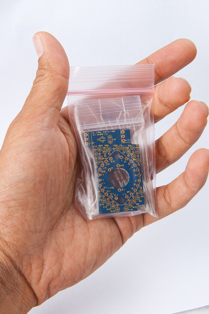
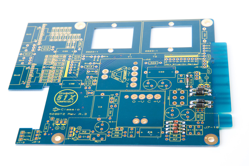
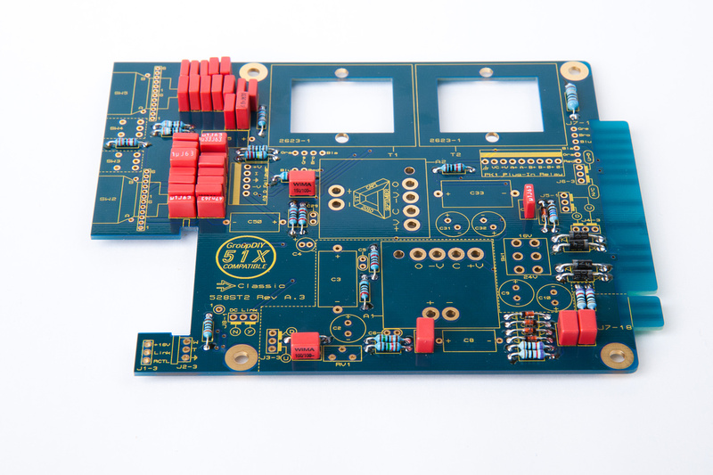
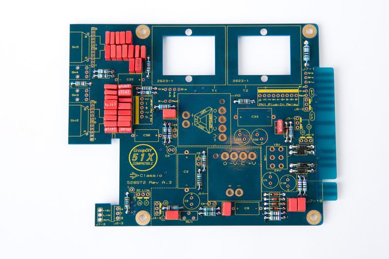
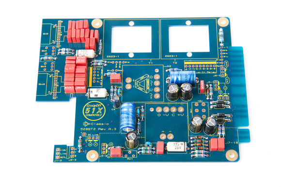
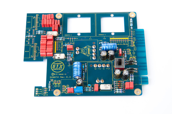
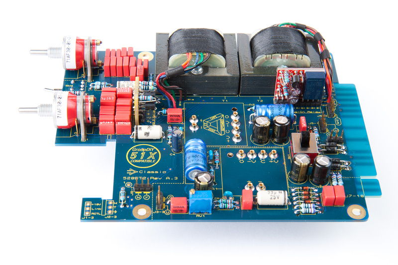
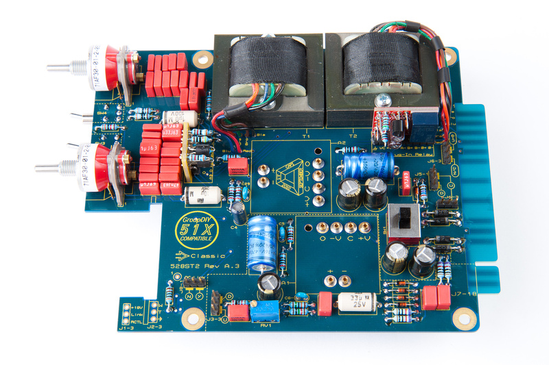
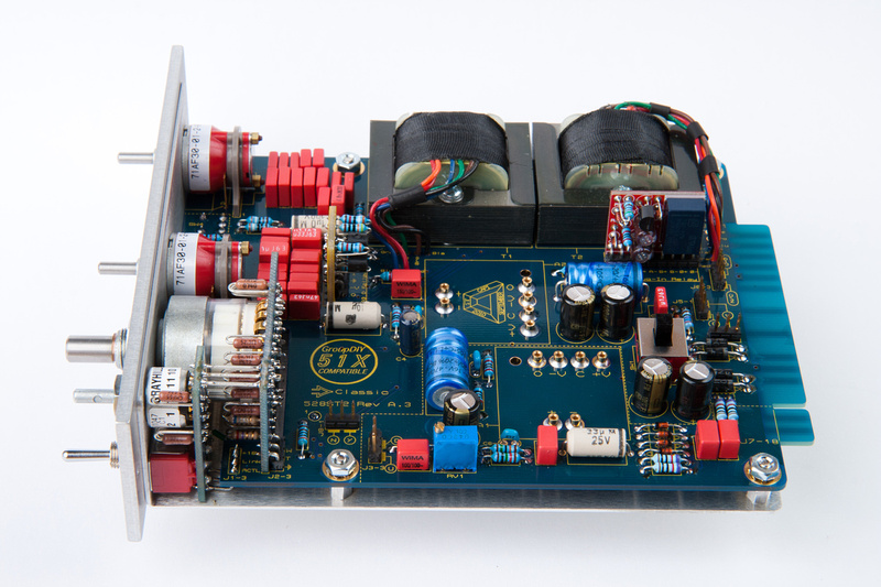
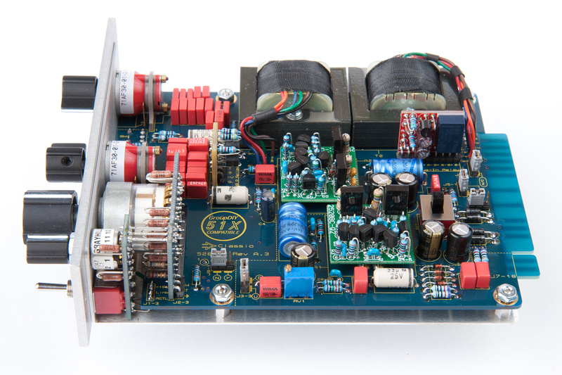
Packages from Classic Audio Products are always shipped with excessively secure packing, so sometimes it's a bit of a chore getting everything out of the box, but once freed from the encasing Styrofoam, here is the VC528 kit. This is the 51x version of the kit. I purchased a stereo pair of these with closely matched resistors between the 2 units. Only one is pictured.
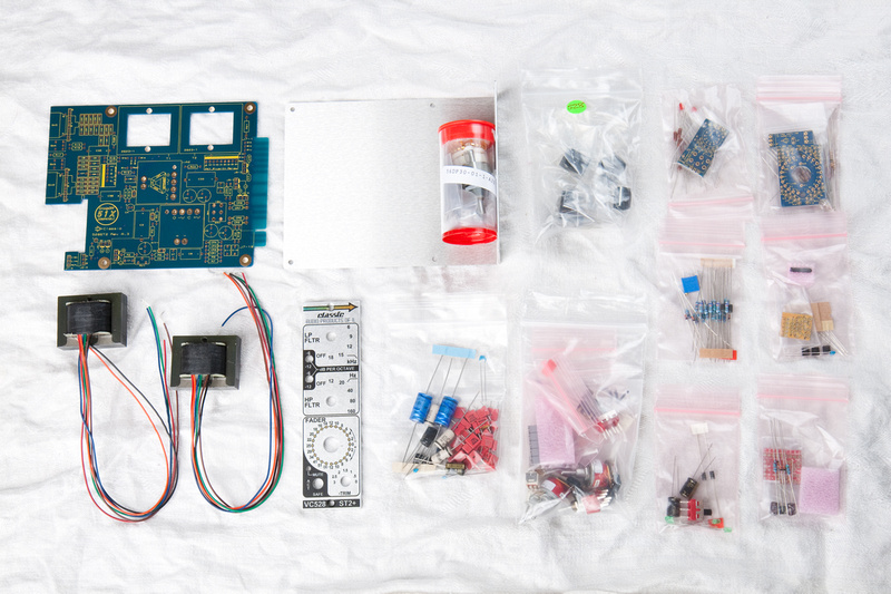
It all looks a bit daunting, but I figure everything is designed to go together in a very intuitive way, and breaking everything down into small, easy steps smooths the way.
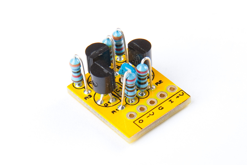
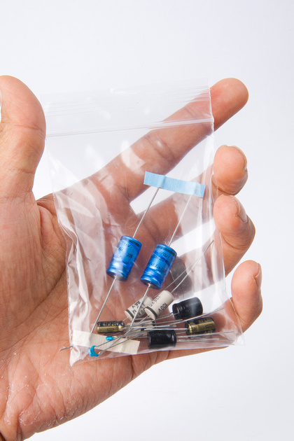
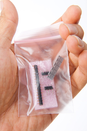
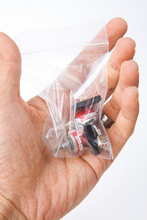
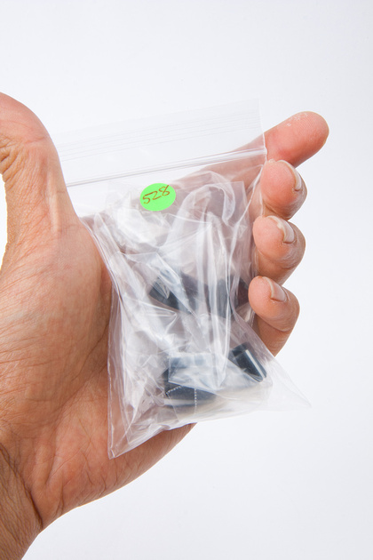
Going by the preliminary build documents, the "discrete follower" sub-board should be assembled first. It is contained in this baggie.
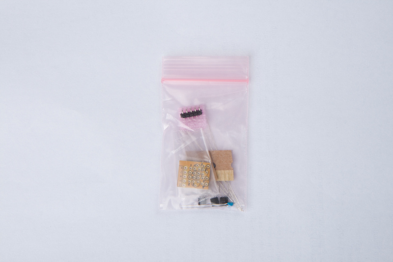
build document "1_DF.1-layout.pdf" identifies and locates all of the components. I start by sorting the parts:
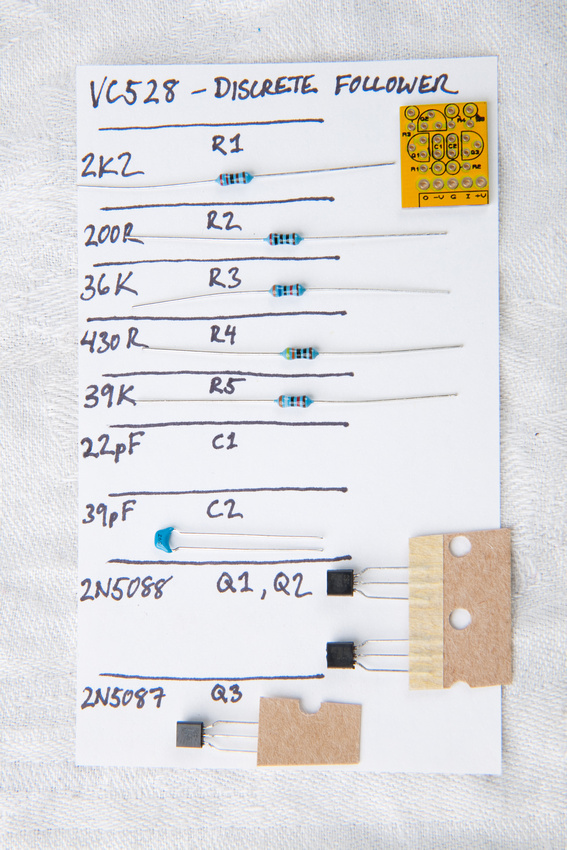
Note: C1 is not used or included
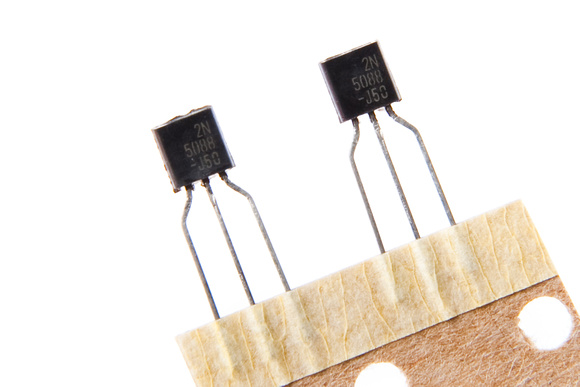
Closeup of Q1 and Q2
Closeup of Q3

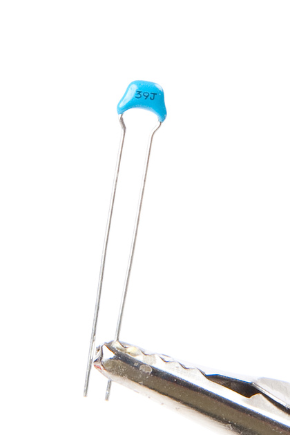
Closeup of C2
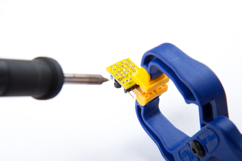
I set myself up on a vise to solder most of these components.
Populating. . .
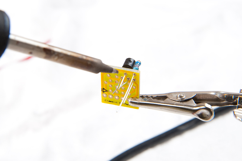
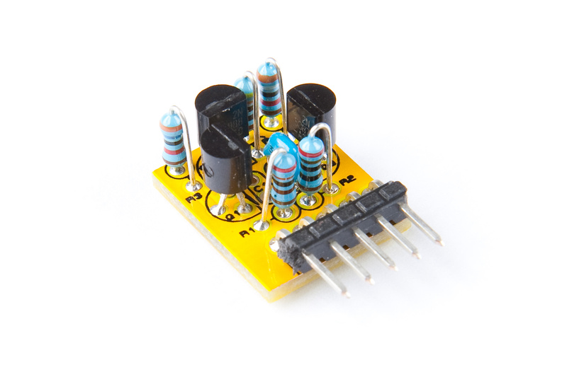
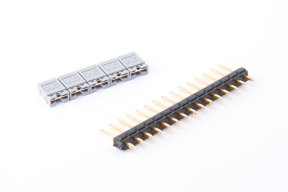
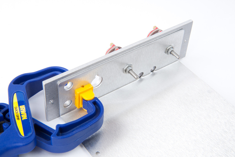
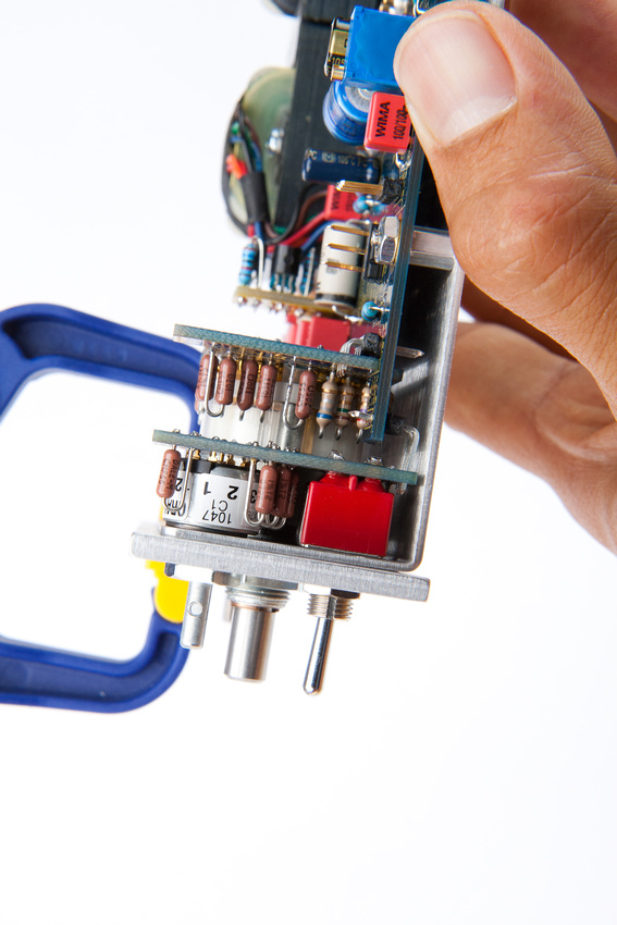
To solder in the L header, I used a clamp which left 2 leads exposed.
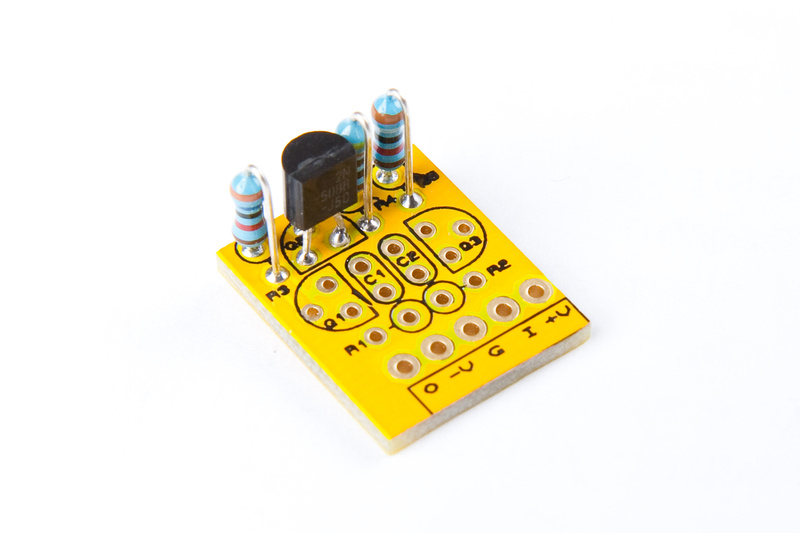
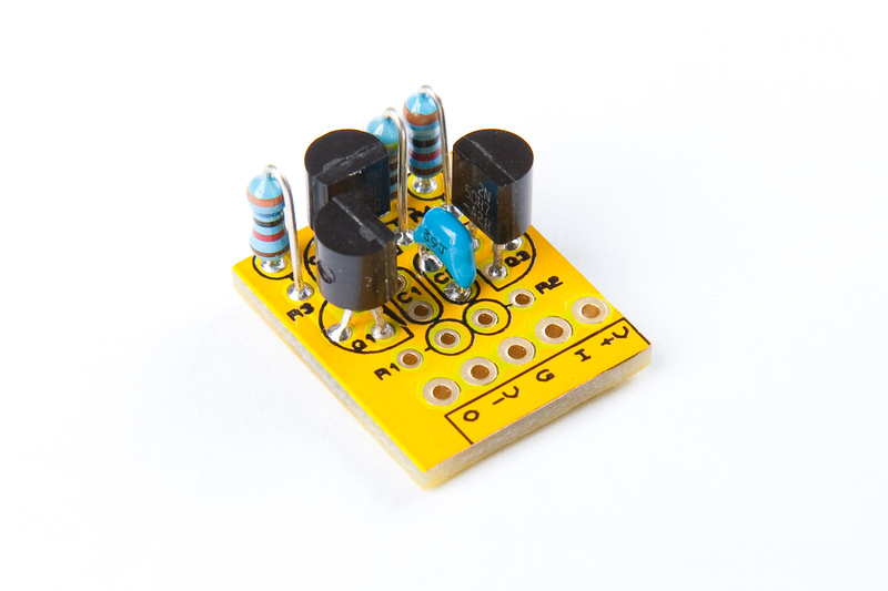
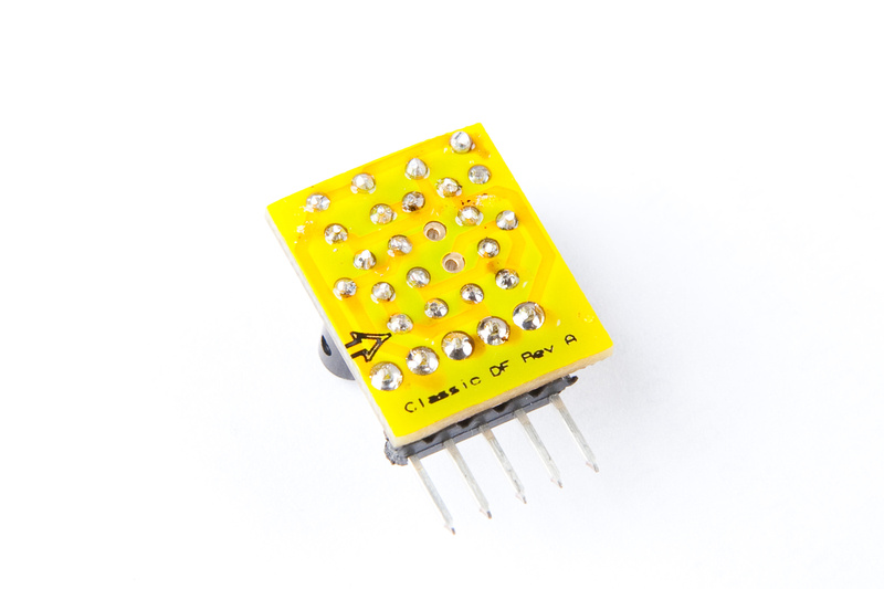
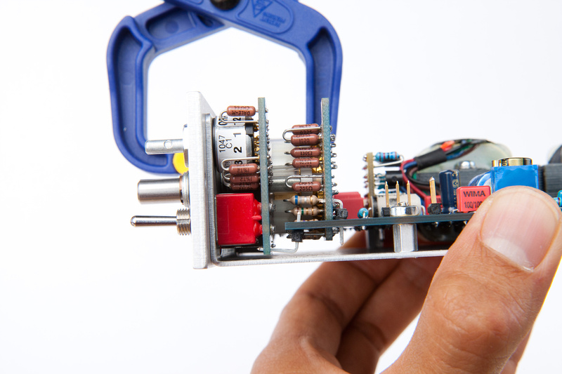
And, component complete:
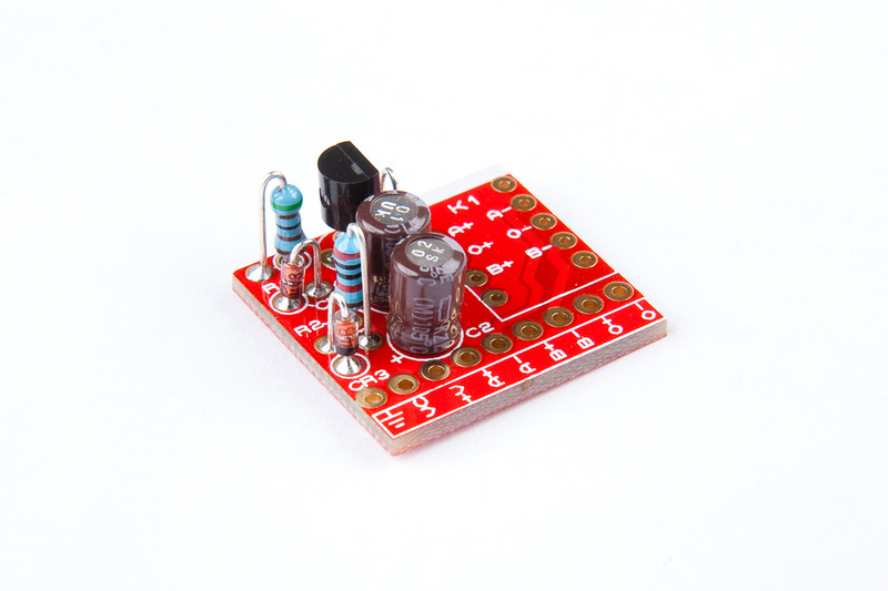
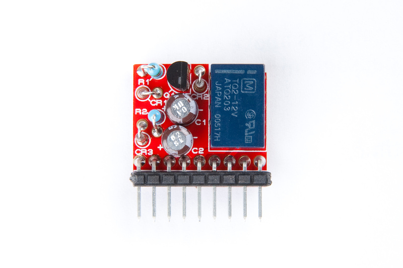
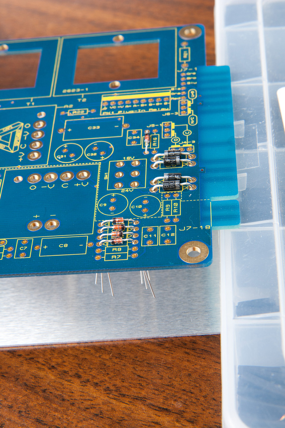
Next up, the relay board. . . details on components and placement are on "2_Plug-In-Relay.1-layout.pdf" in the support docs.
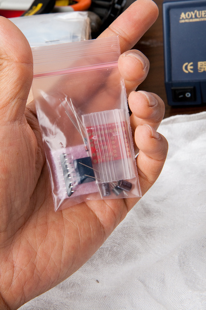
The relay board will be found in this baggie:
And, as usual, I sort and identify my electronic components first.
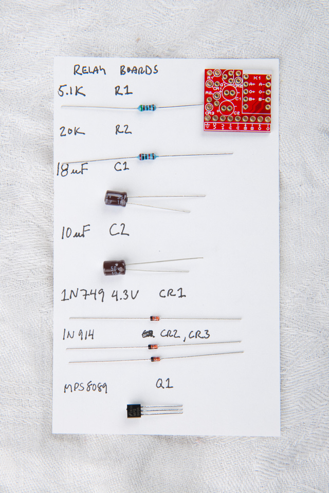
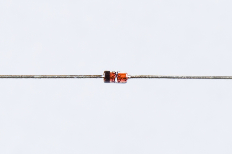
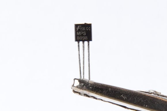
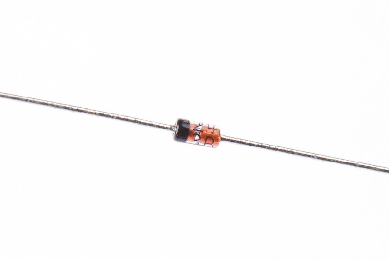
Careful about a couple of the diodes. The markings are tiny. CR1 is marked like this:
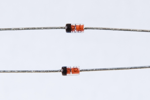
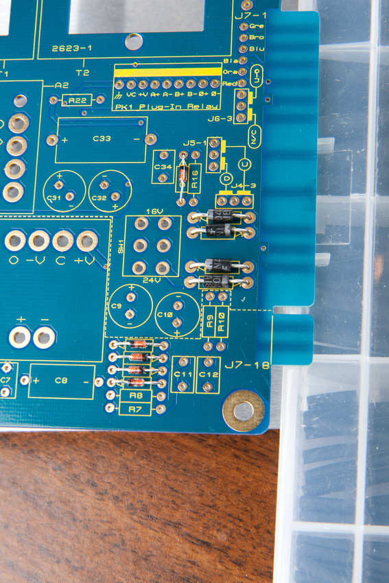
CR2 and CR3 are like this:
and what the heck. . . Q1
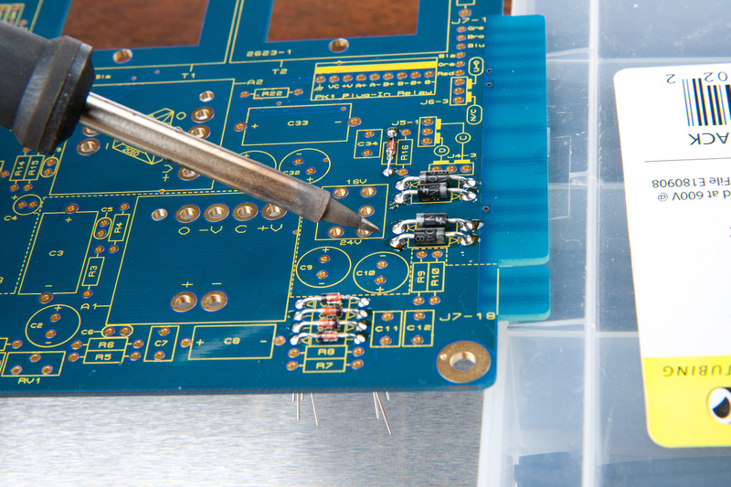
Populating. . .
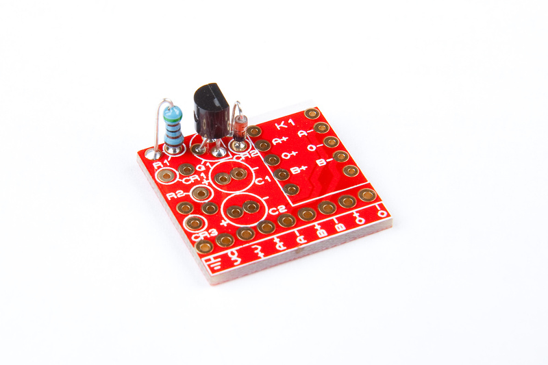
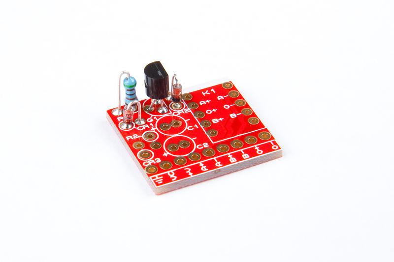
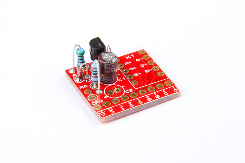
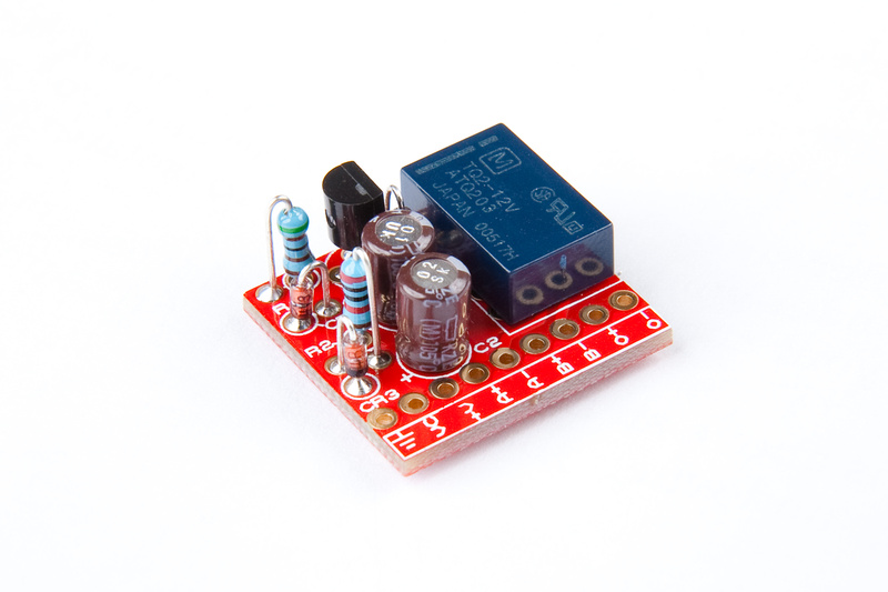
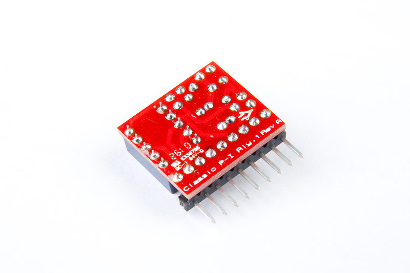
Again, I used a clamp to put the L-header on:
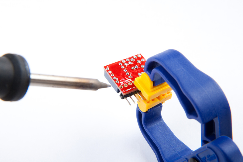
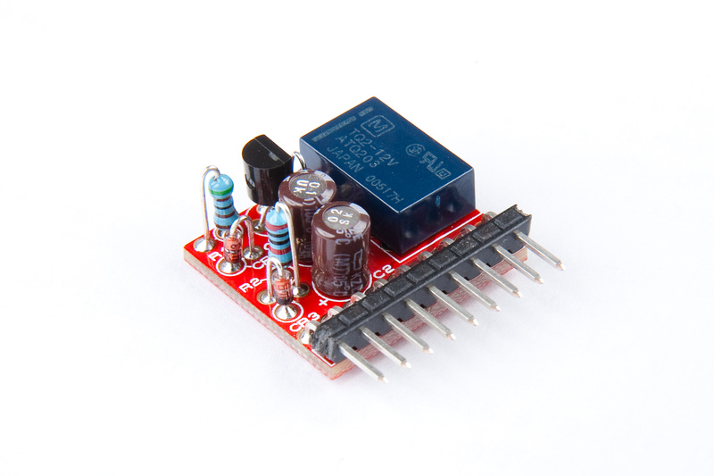
And, component complete:
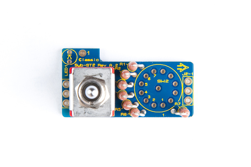
Next on the menu is the sub-ST2 board. Details about this board can be found in:
"8_04-1x24 Rev A_Sub-ST2 Rev A.2 Overlay.pdf" and "7_Classic VC528 Sub-ST2 PCB BOM.pdf" in the build documents.
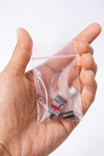
The components for the Sub-ST2 board can be found in this baggie:
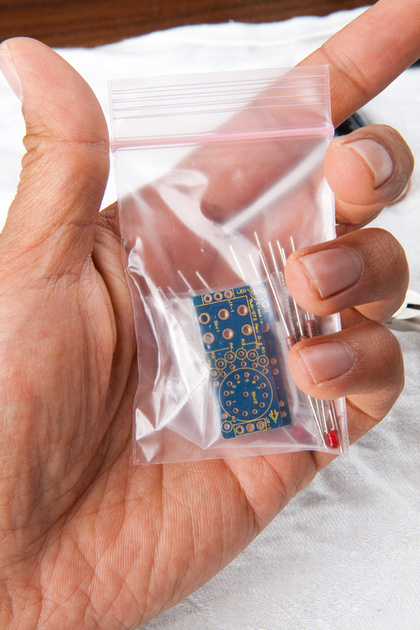
Note, in the stereo kits, you'll find 2x pcb's and a closely matched set of resistors in this baggie.
Next, I identify and sort the electronic components. For our build, even though I'm doing a stereo pair, I'm showing components for a single board in the photo. . . just to keep things consistent.
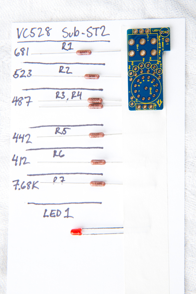
These resistors are very easy to identify because the values are all printed at a pretty reasonable size. I double check them all with my multimeter just to be safe.
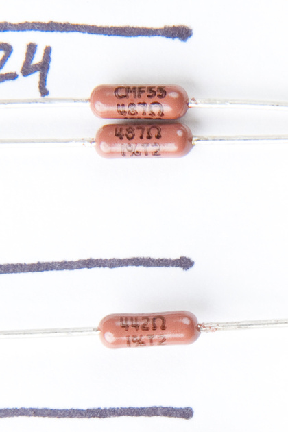
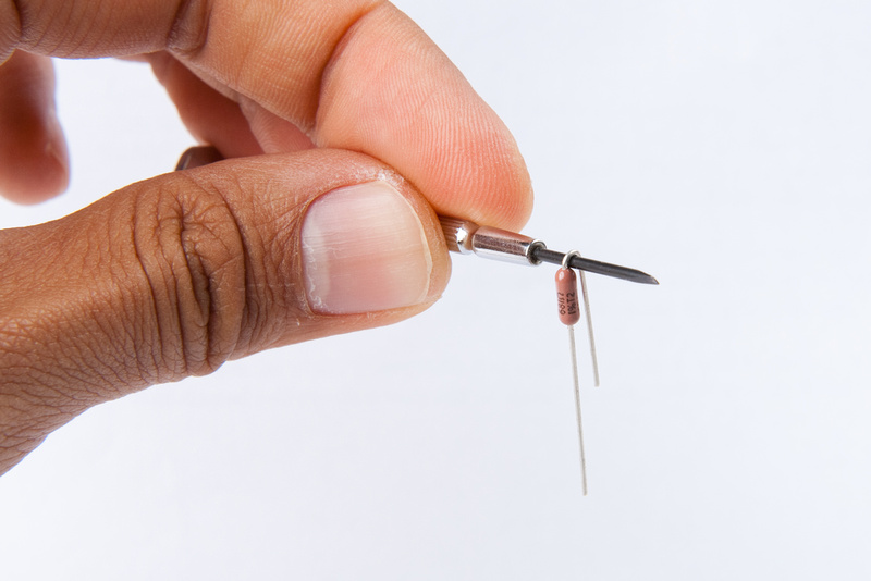
Here's a little trick I learned from the draft instruction PDF jsteiger wrote up to make clean, consistent bends on the resistors using the shaft of a small screwdriver. Worked great!
and, we're populating.
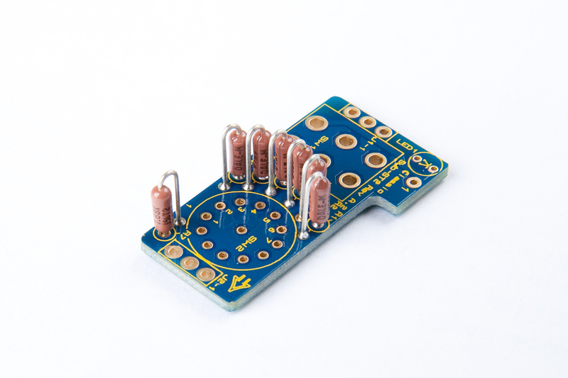
and, a shot showing my resistor values more for personal reference later if I have a problem.
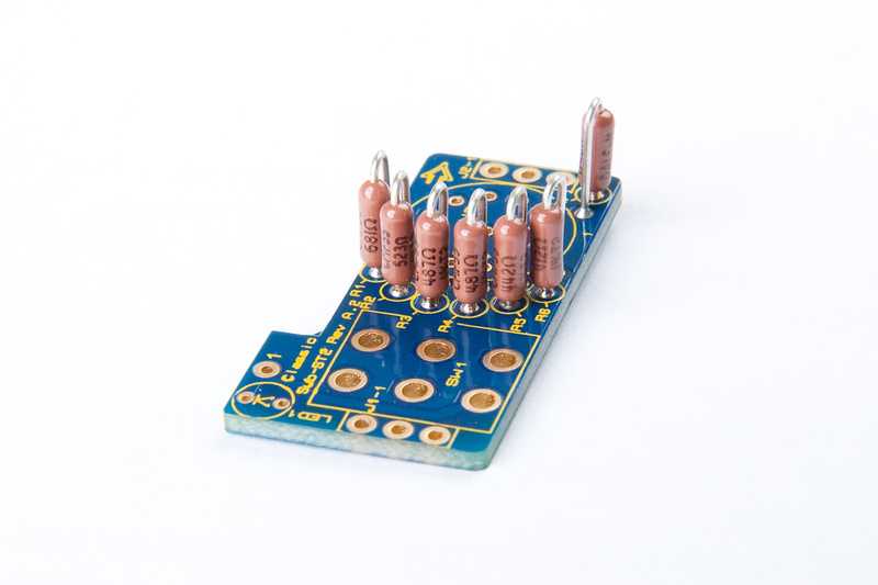
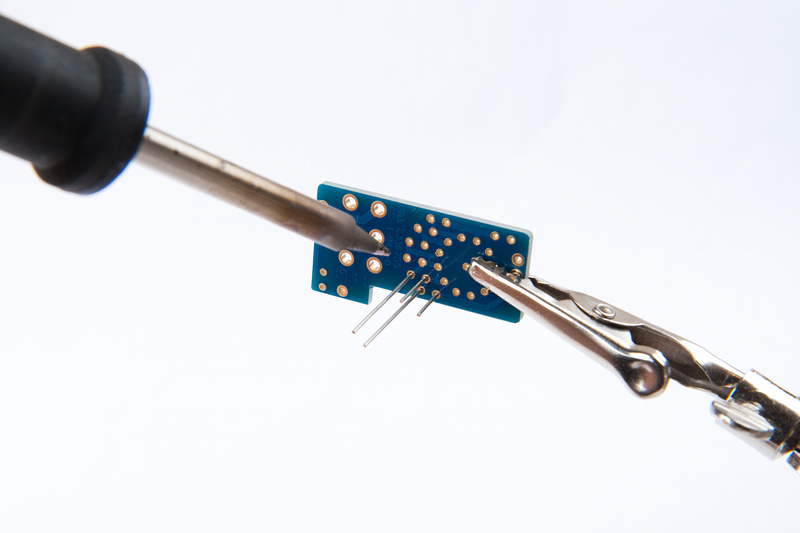
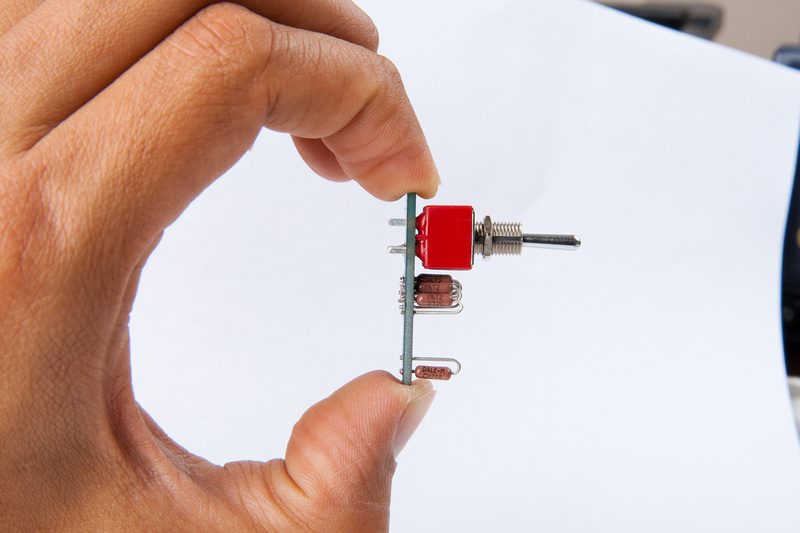
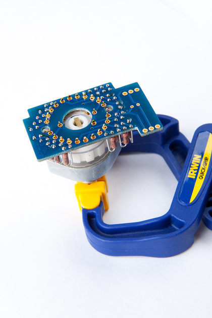
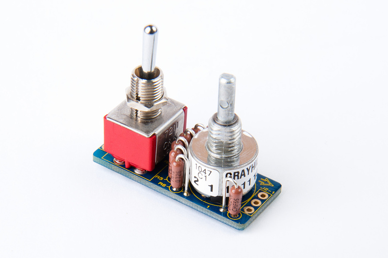
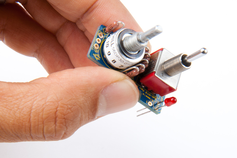
Next we install the 3 position toggle switch. . . the instructions say to make sure and seat this one flush to the PCB and straight. I lightly clamped the threaded shaft of the toggle switch like so. . .
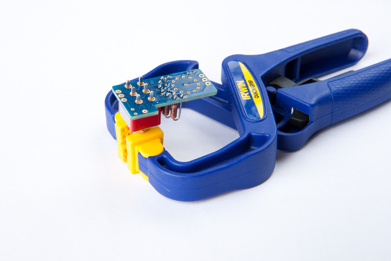
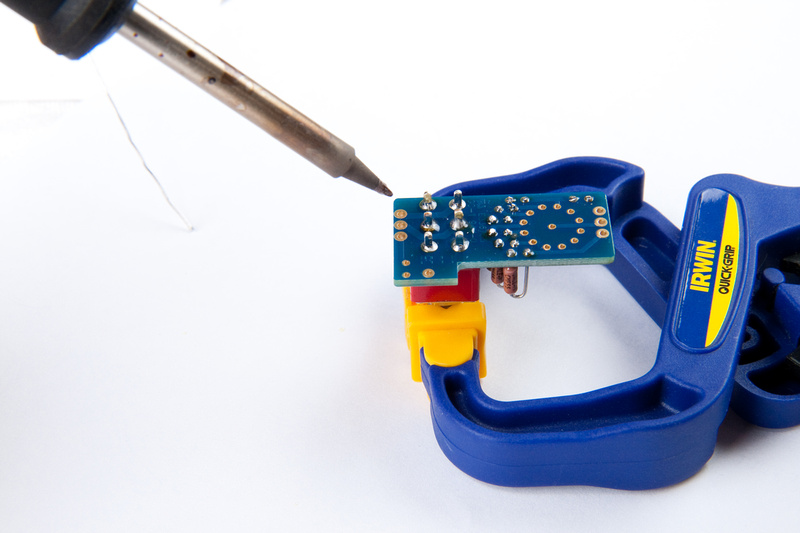
Then, it was a bit of a juggling job, but not too bad. I chose one of the center solder lugs, pressed down with the soldering iron lightly and soldered the joint. . . immediately when the solder melts into the joint, and with the soldering iron still on the joint, I let go of the solder wire, and press the PCB down firmly with my fingers. . . easy. Then, remove the soldering iron and hold the joint until the solder hardens.
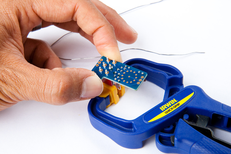
It would have been awesome to have a picture holding the PCB with my left hand, and with the soldering iron actually on the joint, but it was logistically difficult having only 2 hands

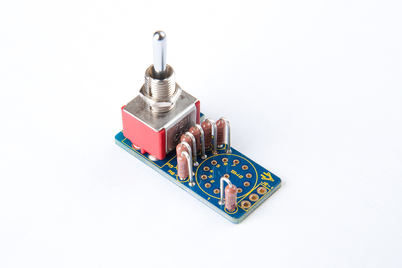
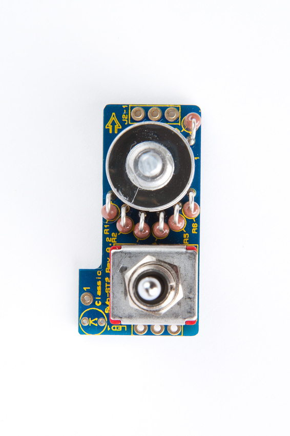
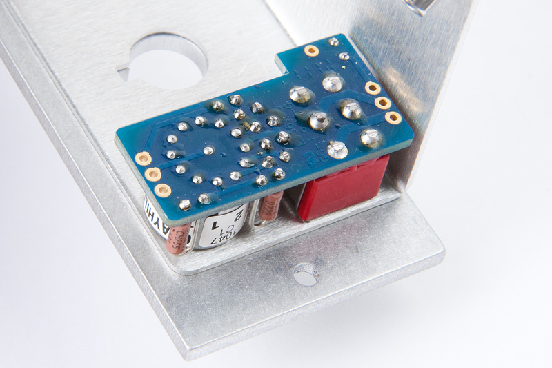
Verify that everything is fully seated. . . nice and straight:
doesn't get much better than that, so I went ahead and soldered the remaining lugs on the switch.
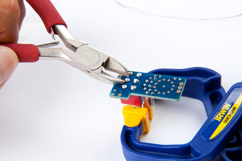
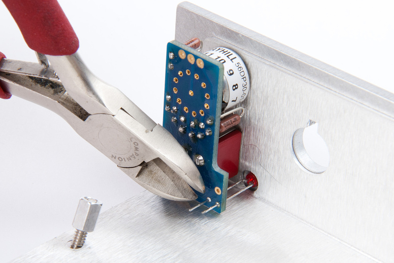
Then, per the instructions, I cut the leads on the switch close to the PCB
OK. . . instruction set says to leave the L-header, LED, and Grayhill switch off for later steps, so we are done with this component for now.
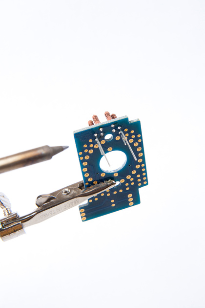
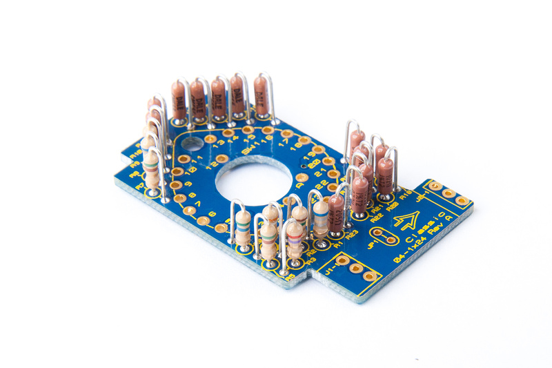
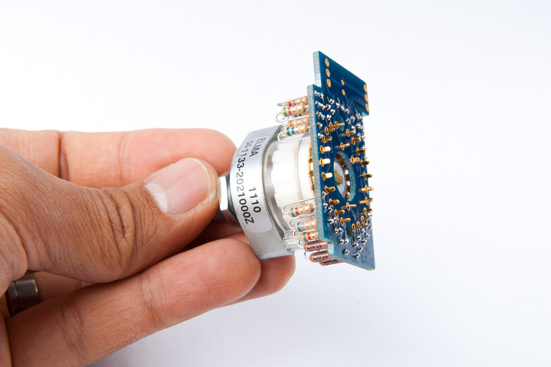
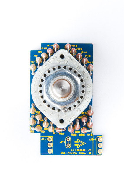
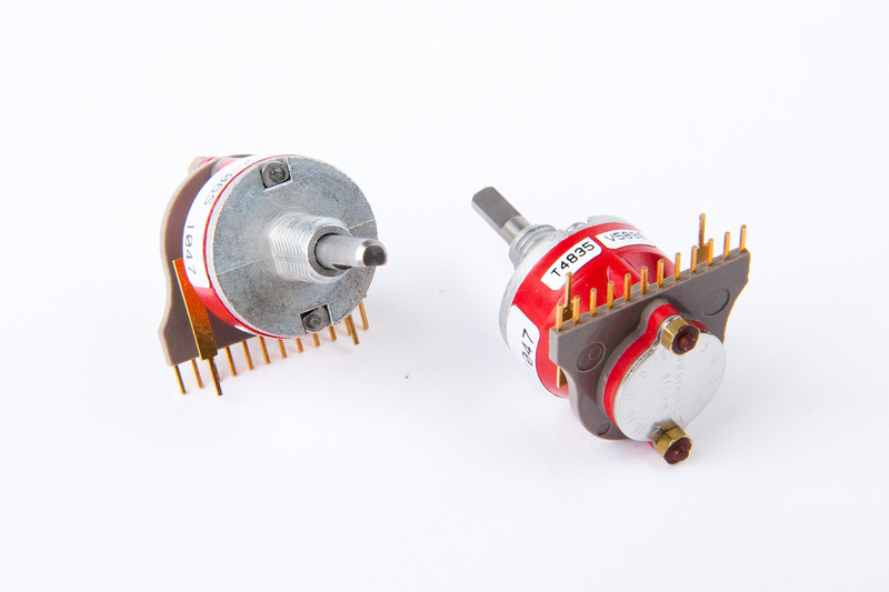
Next up in the build is the Elma switch sub-board. The parts are contained in this baggie:
There are a lot of resistors to sort in this little board. Here are the parts identified, sorted, and ready to go.
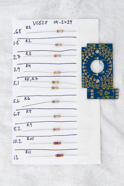
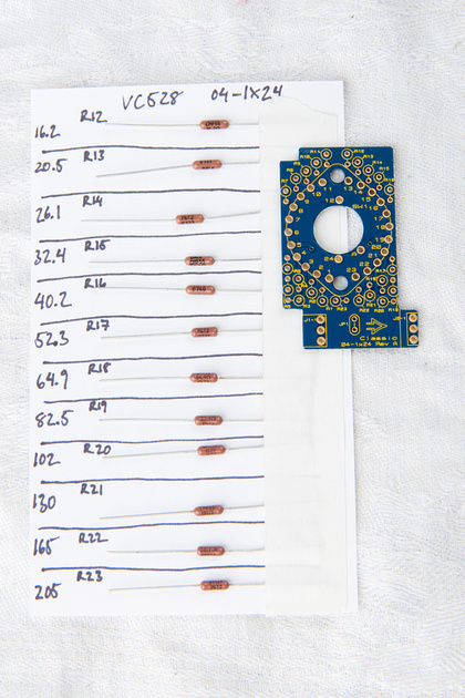
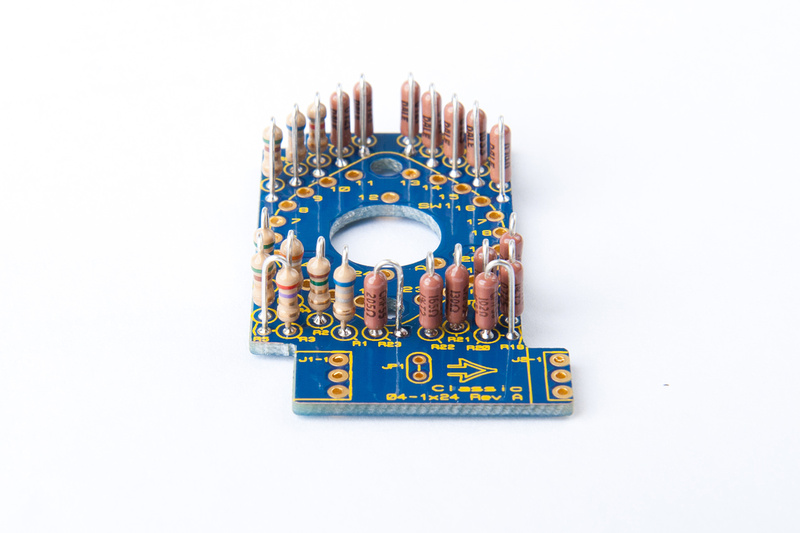
and, we're populating in the order specified in the build manual. . .
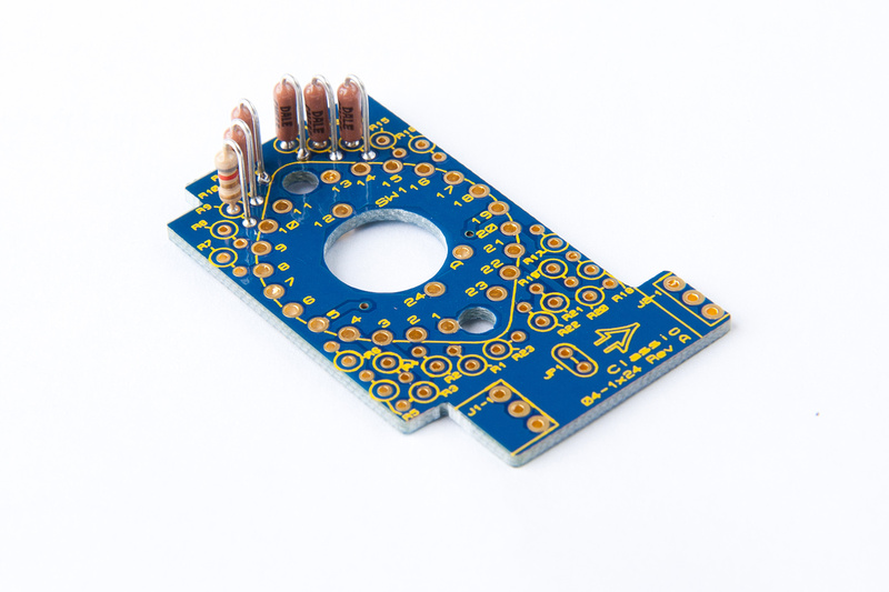
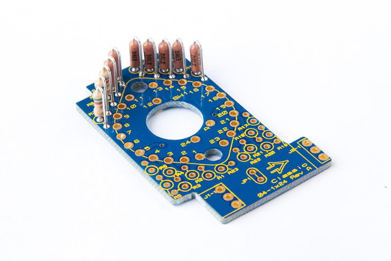
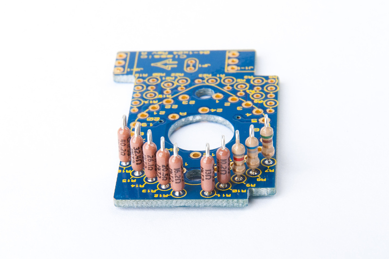
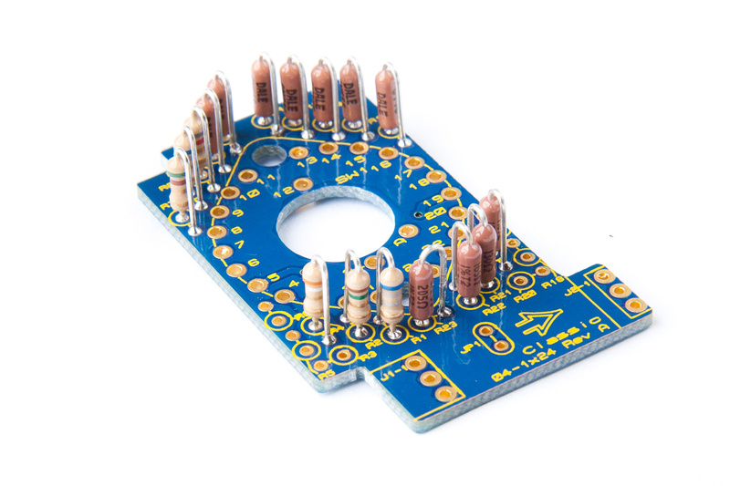
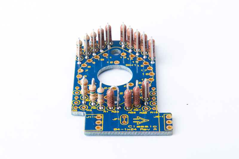
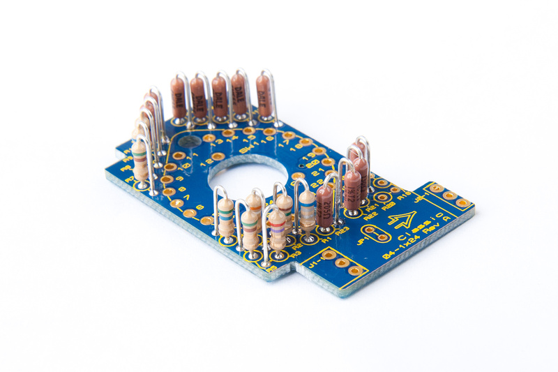
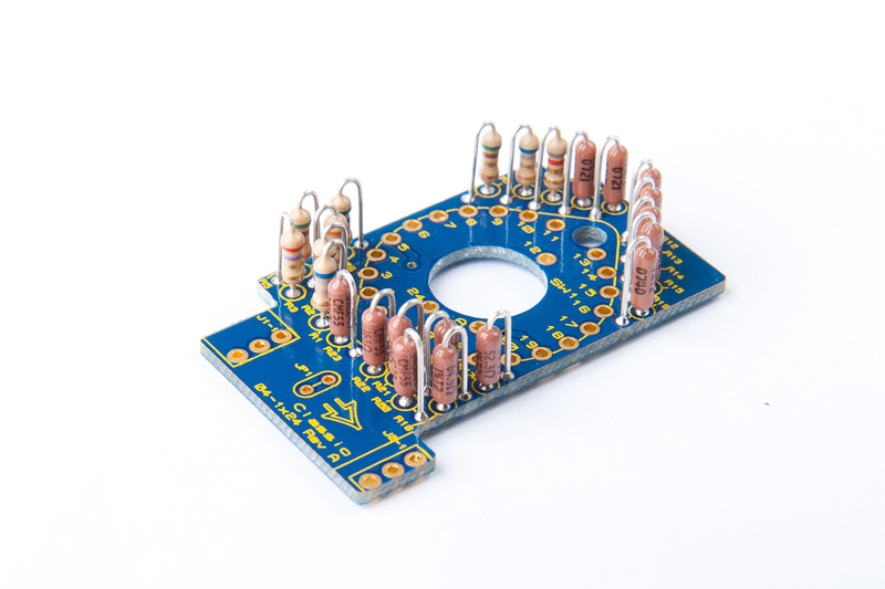
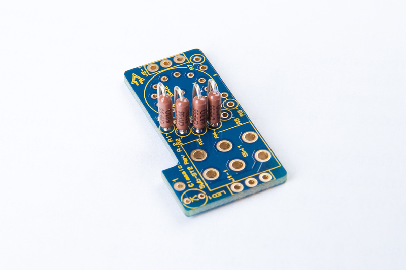
and, all resistors are placed.
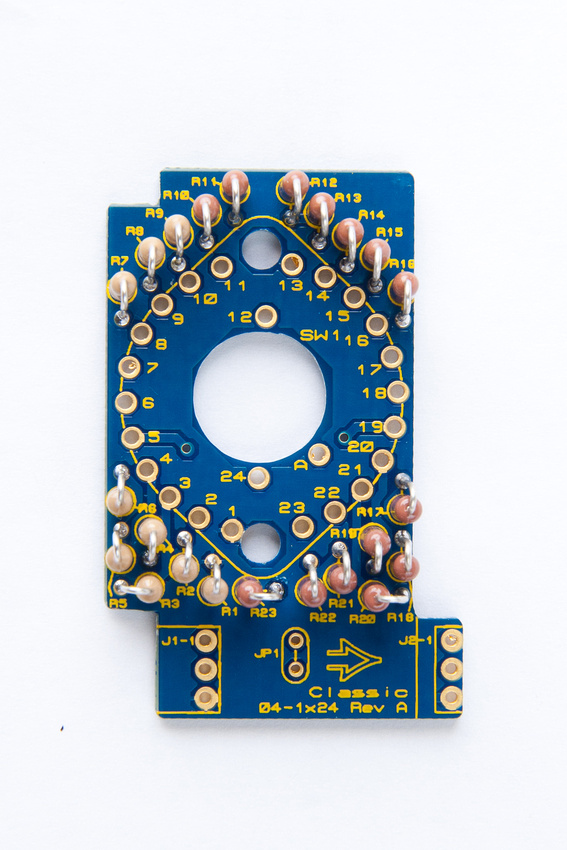
Next, I check resistance between J1-2 and J1-3 looking for 1K ohm to make sure I did not bridge any solder joints.
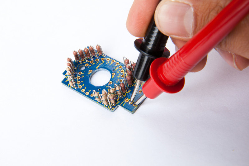
and we're good to go.
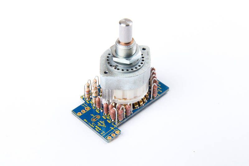
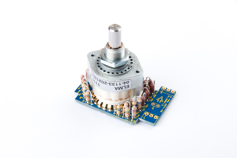
The Elma switch is placed. . . a few pins needed to be slightly nudged into position before pressing into the PCB.
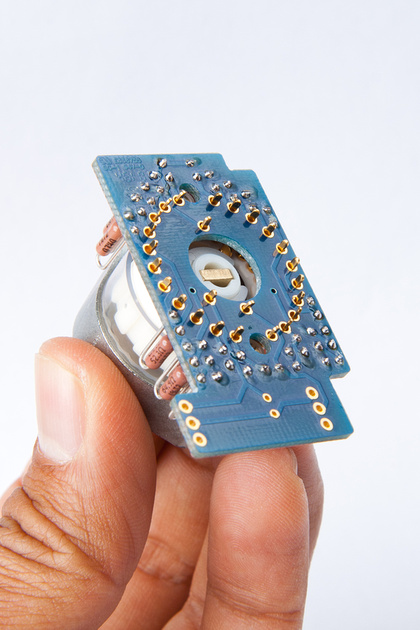
And, here is how I set up to solder the switch
And, Elma switch is in.
I checked resistance again between J1-2 and J1-3 to confirm we are still at 1K ohm, and this sub-assembly is ready to go. We set it aside for now.
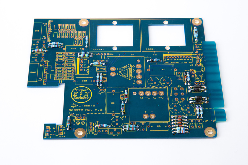
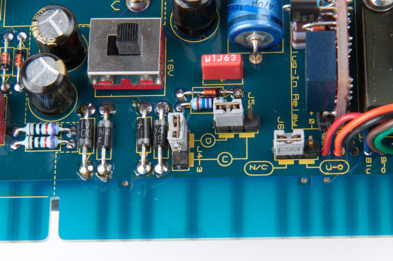
Next, I move to the main PCB starting with the diodes.
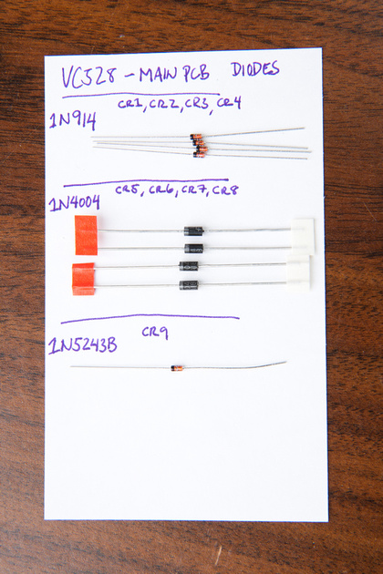
Watch out for the 1N914 CR1, CR2, CR3, and CR4. . . these look like this:
Also, watch out for 1N5243B CR9. . . it's marked:
24
3B
Next, I placed the components on the PCB as marked.
And, soldered the components in from the top side.
And, diodes are done.
Next up, I use a printout of the provided resistor sorting PDF to sort the main PCB resistors.
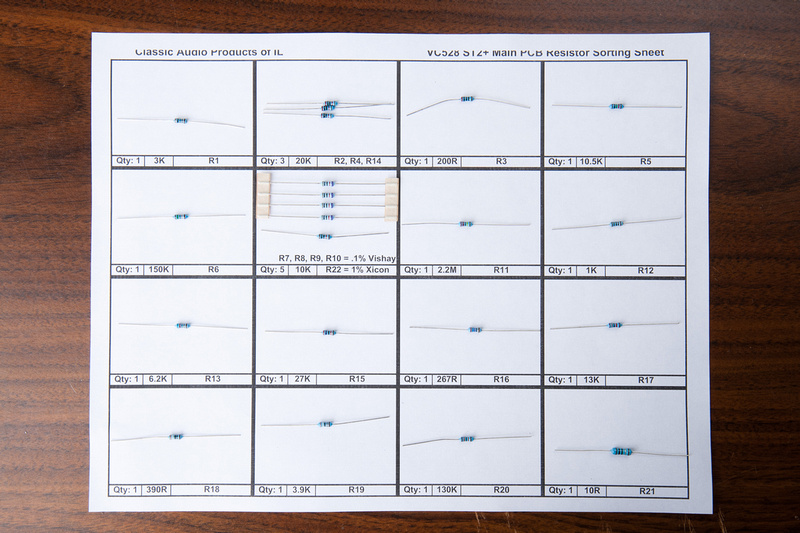
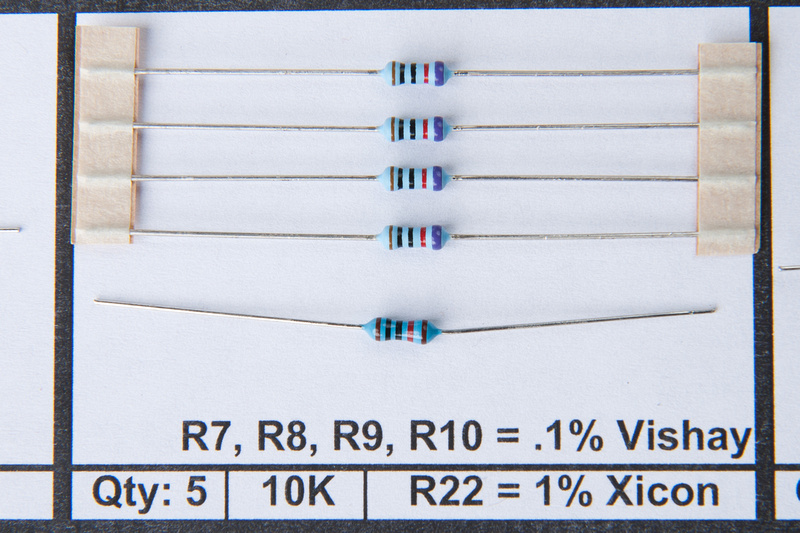
Note: R7, R8, R9, and R10 are packaged together and are .1% Vishay. . . R22 is the same value, but 1% Xicon
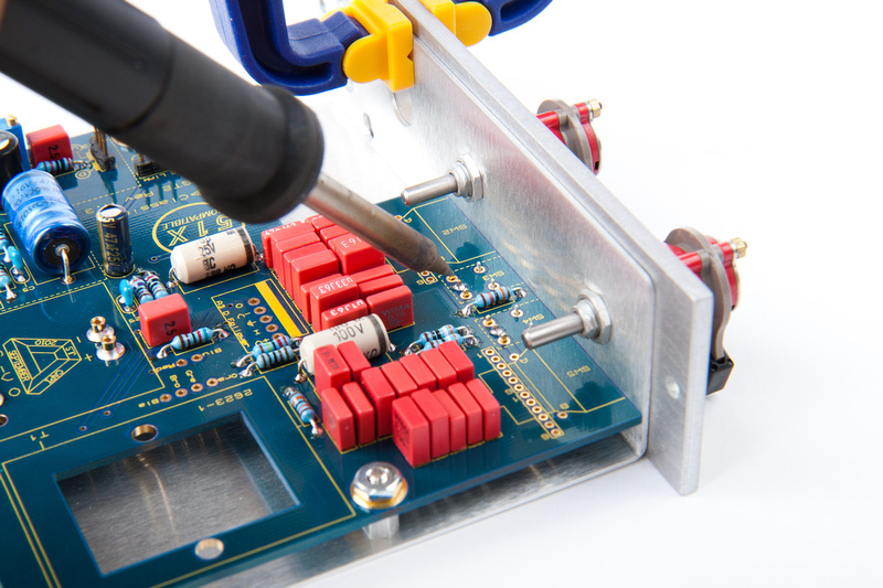
I then place all resistors on the PCB.
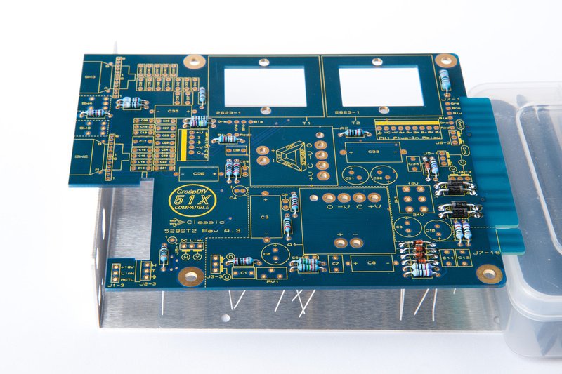
and solder from the top side cleaning up joints as needed from the back side.
Note: R7, R8, R9, and R10 are packaged together and are .1% Vishay. . . R22 is the same value, but 1% Xicon
I then place all resistors on the PCB.
and solder from the top side cleaning up joints as needed from the back side.
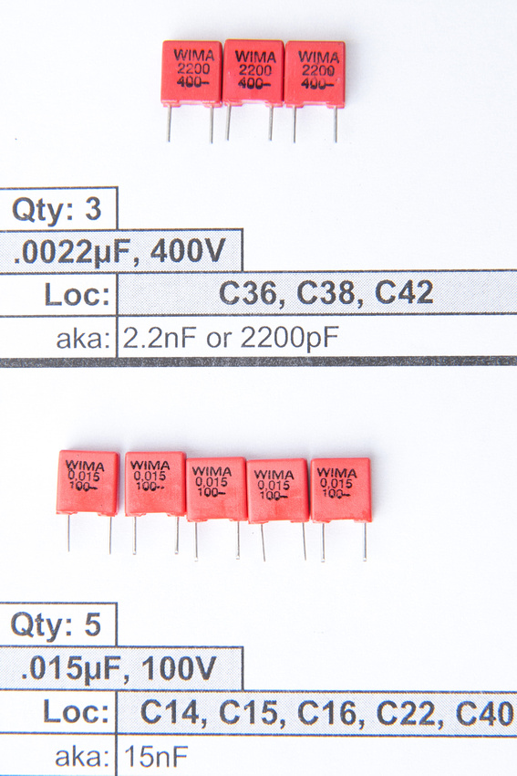
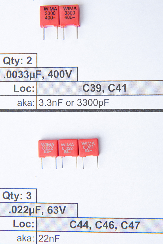
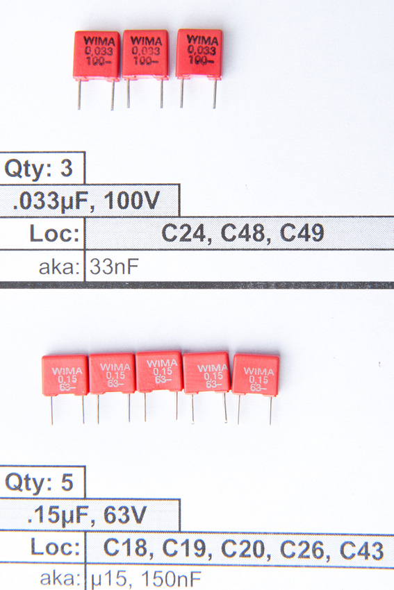
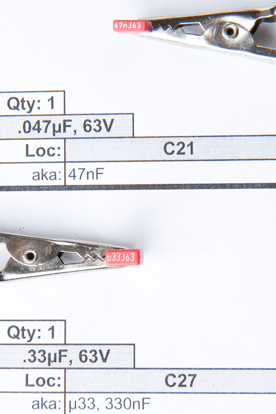
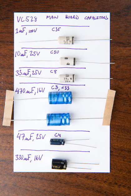
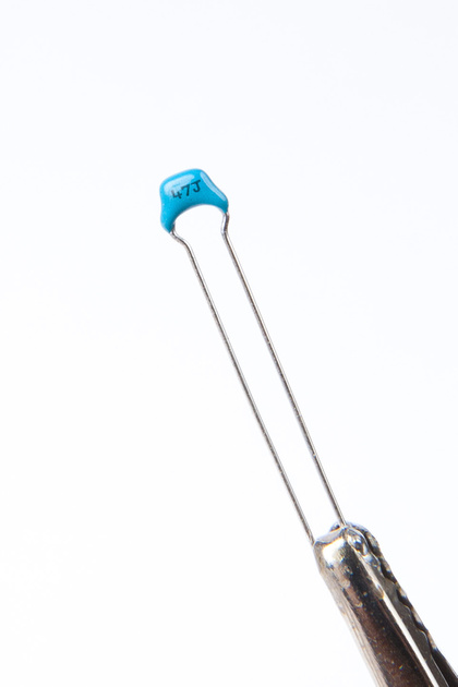
Next up, I use a printout of the provided film capacitor sorting PDF to sort capacitors.
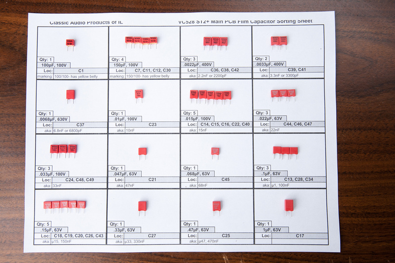
Due to possible confusion on the various labeling conventions on these capacitors, I'm including pictures of the markings. I ended up having C21 (.047uf) and C25 (.47uf) mixed up on the first pass, so please double check!
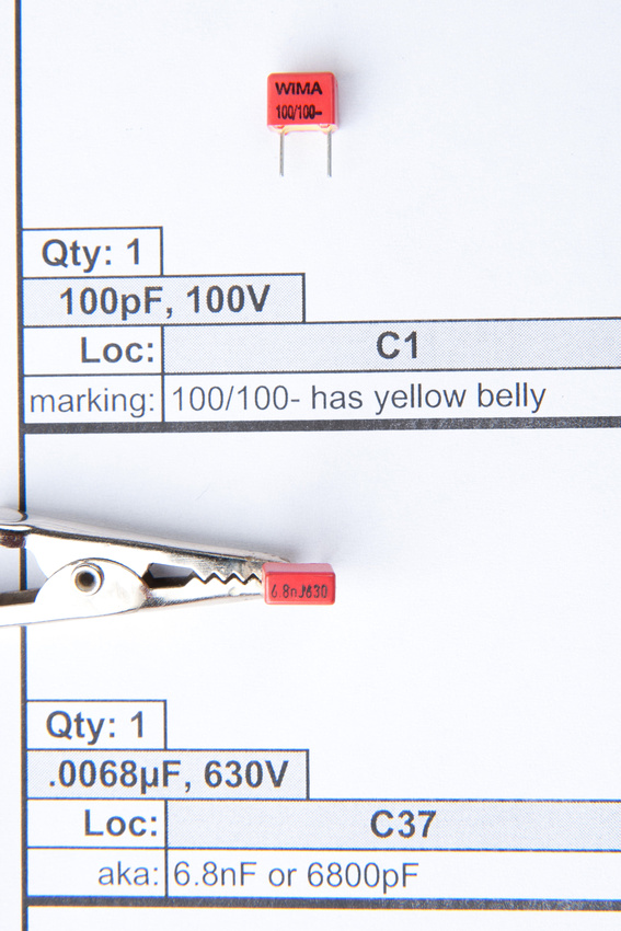
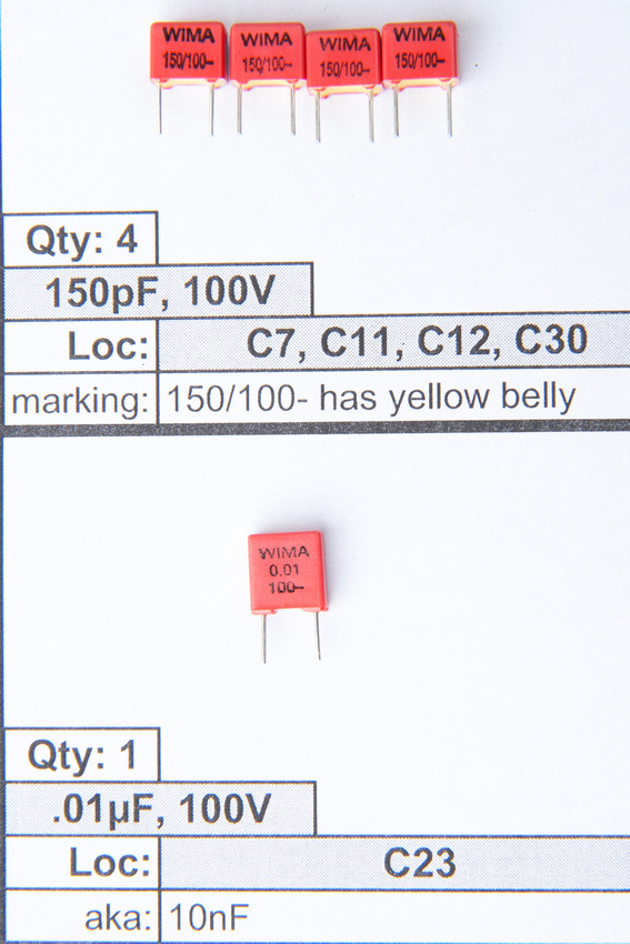
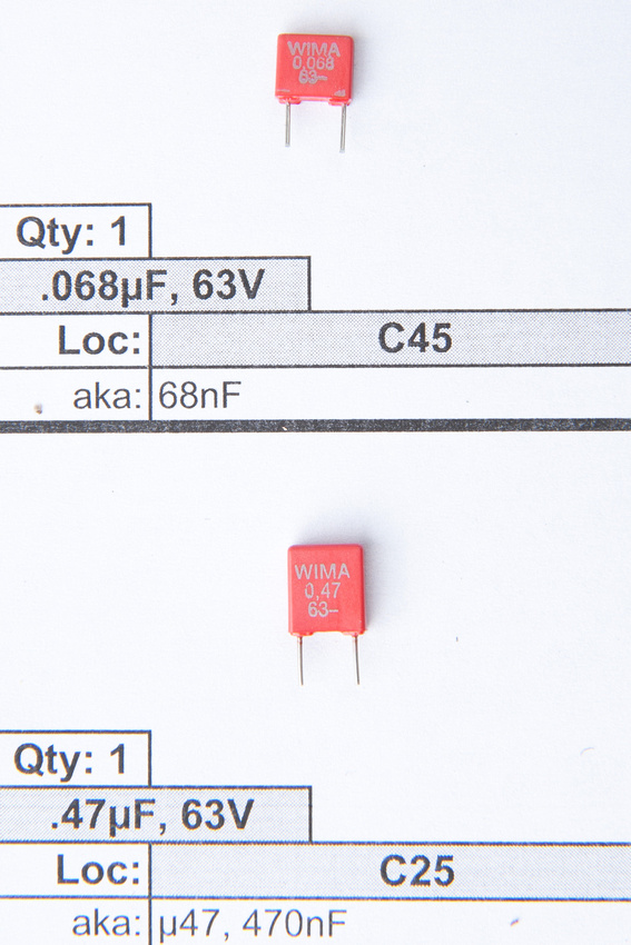
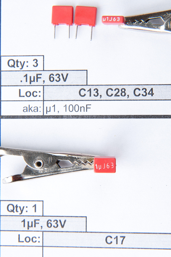
Due to possible confusion on the various labeling conventions on these capacitors, I'm including pictures of the markings. I ended up having C21 (.047uf) and C25 (.47uf) mixed up on the first pass, so please double check!
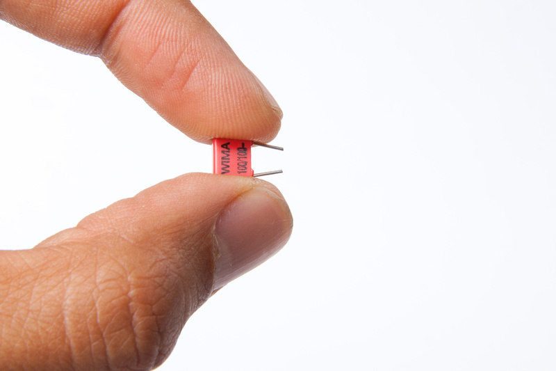
Having sorted the film capacitors, it's time to stuff them into the PCB. On this point, I think there are better ways of doing things, as I'm not 100% happy with how straight my caps ended up lining up on the PCB, but for what it's worth, here's how I did it.
First, I bent the legs of the caps a little.
Then, I inserted into the PCB and soldered 1 leg (I can seldom get the caps to seat firmly against the PCB by bending the legs).
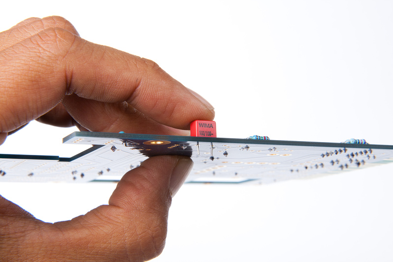
Then, with the PCB on it's side, I solder 1 leg of the film cap.
(note: no picture of the next steps because i couldn't figure out how to do it without hurting myself or breaking something).
Next, I re-heat the 1 soldered leg while applying pressure to the cap with my finger seating the cap. . . then, with the cap secured in position, I flip over and solder the 2nd leg.
At any rate, here is the board populated with the film caps. (not as straight as I'd like, but nothing wrong with it either)
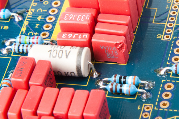
Let's dig up the rest of the caps for the main PCB
Identifying parts again:
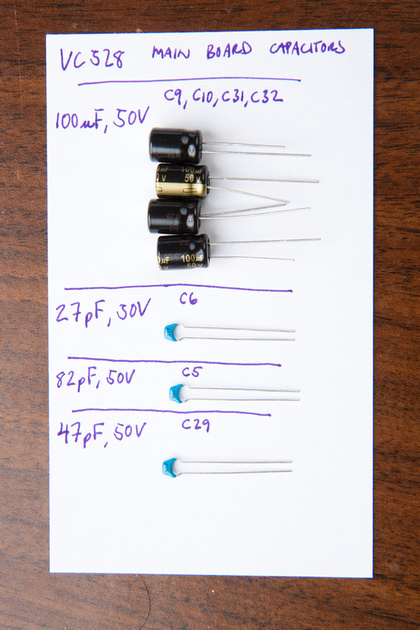
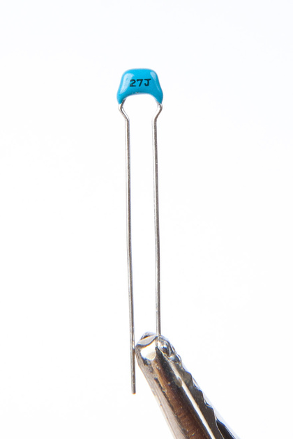
C6 27 pF
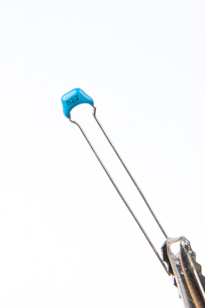
C5 82pF
C29 47pF
Watch the polarity of the electrolytics. The "-" side is indicated with a solid stripe.
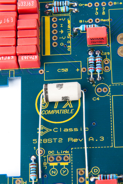
And, sidenote here, I managed to melt C20 when I attempted to touch up a solder joint on the front side of the PCB. . . trying to make all perfect solder joints for pictures. . . oh well. Jeff has been contacted for a replacement WIMA. In the meantime, since I have 2 kits for a stereo pair, I went ahead and replaced C20 w/ one from the other kit, and the build goes on!
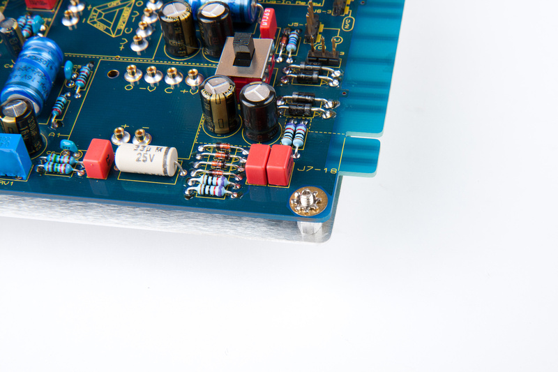
Caps installed.
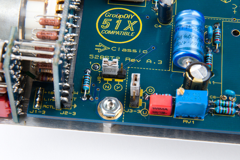
Next, I place the trimmer pot RV1
And SW1
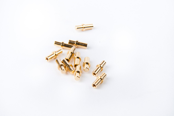
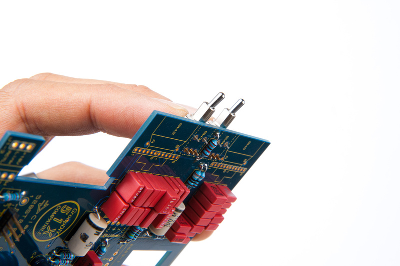
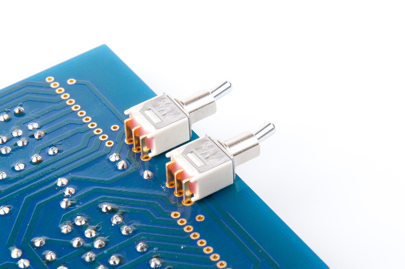
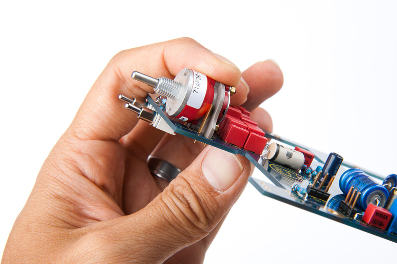
Next, I install the millimax pins for the DOA's. They are found in this baggie. . . watch out. These little critters like to run away, and I once spent an hour looking for one on the ground from a VP26 build.
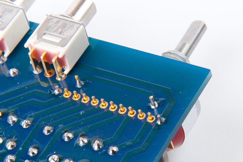
Insert these from the back side of the PCB.
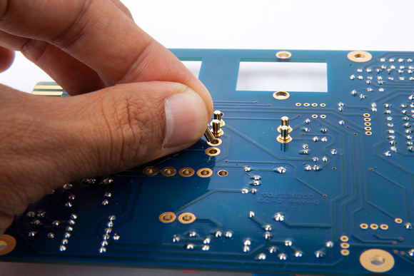
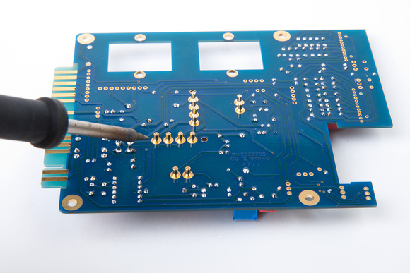
And, solder from the back side. I set my iron a bit hotter and made sure to flow a proper amount of solder to make these solid as some op amps need to be pressed in pretty hard to seat, and I like these sockets to have a solid mechanical connection to the PCB.
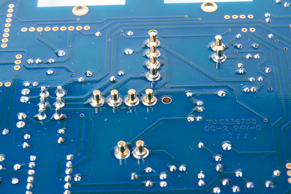
And, this is how they look from the front side after getting soldered in.
And, the main PCB is populated. Humans win.
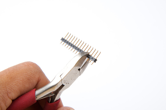
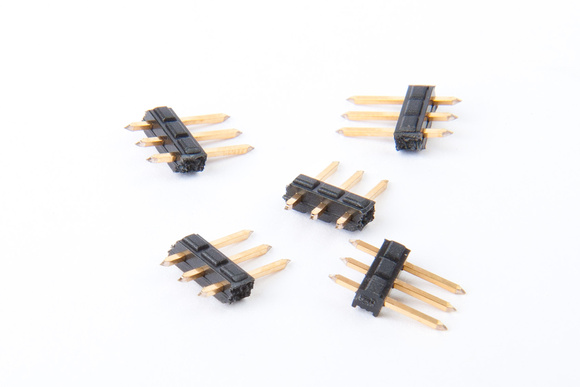
Next up, I install my 3 pin headers for configuring the VC528. These headers and jumpers are found in this bag:
This will need to be cut into 5 separate 3 pin units.
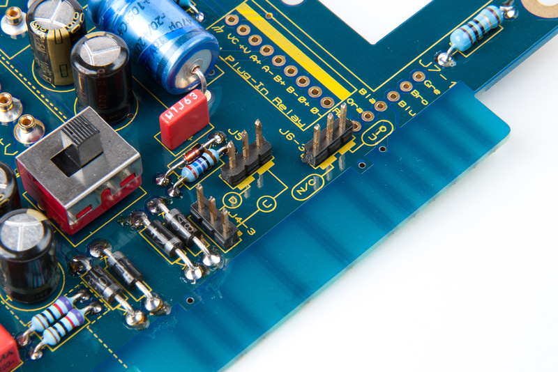
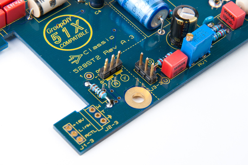
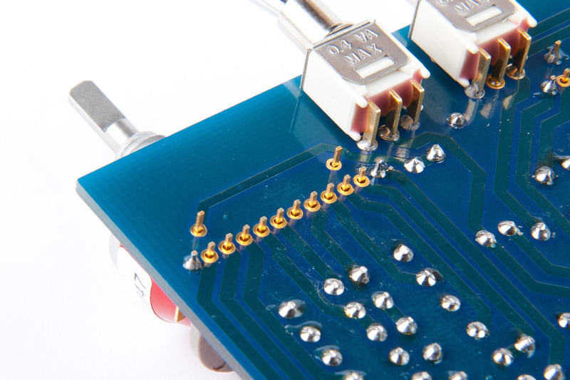
And installed in these locations taking precaution to stand them up perpendicular to the PCB.
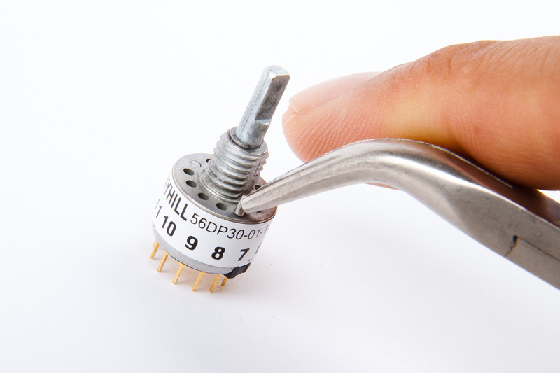
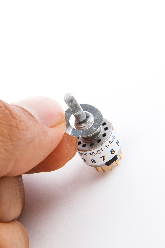
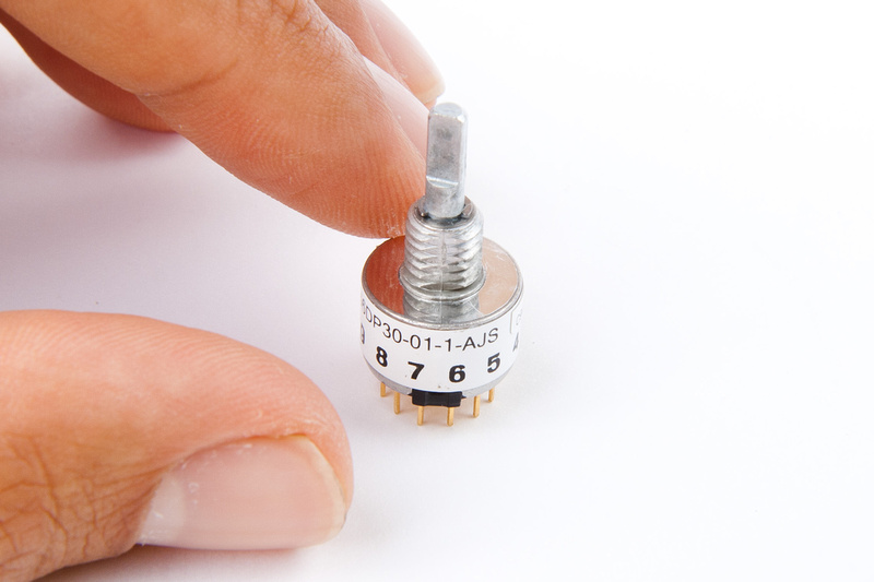
For the next step, I will need my grayhill switches found in this baggie:
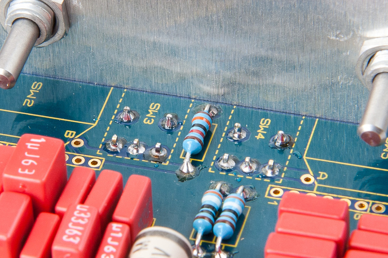
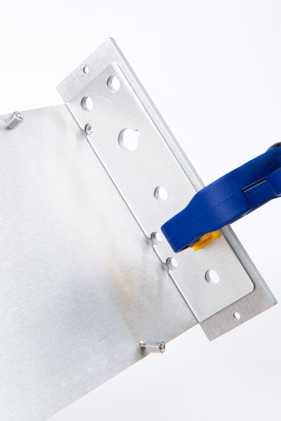
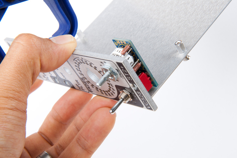
And use these installed from the front side to align my faceplate to the L-bracket.
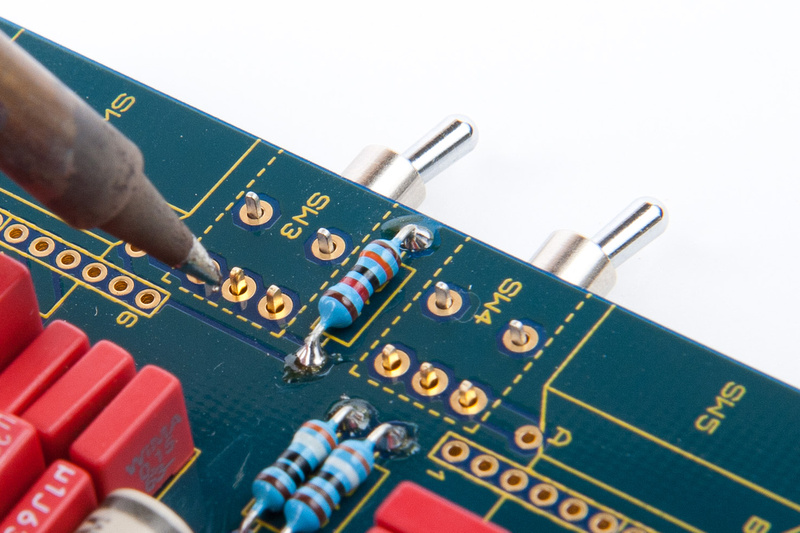
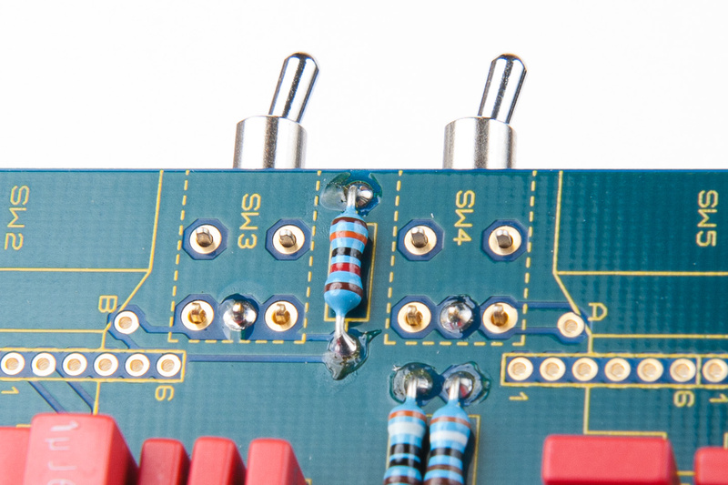
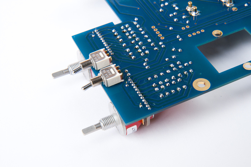
This will facilitate lining up the mini toggle switches SW3 and SW4
Holding the switches firmly in place, solder the center lug only.
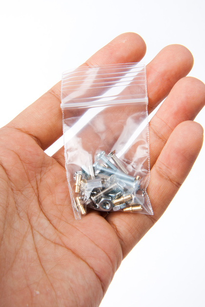
Next, locate the PCB mounting hardware.
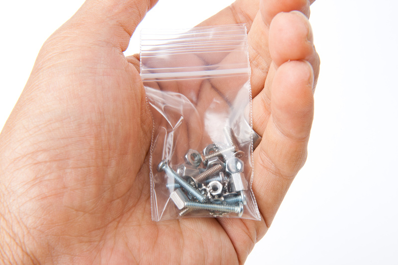
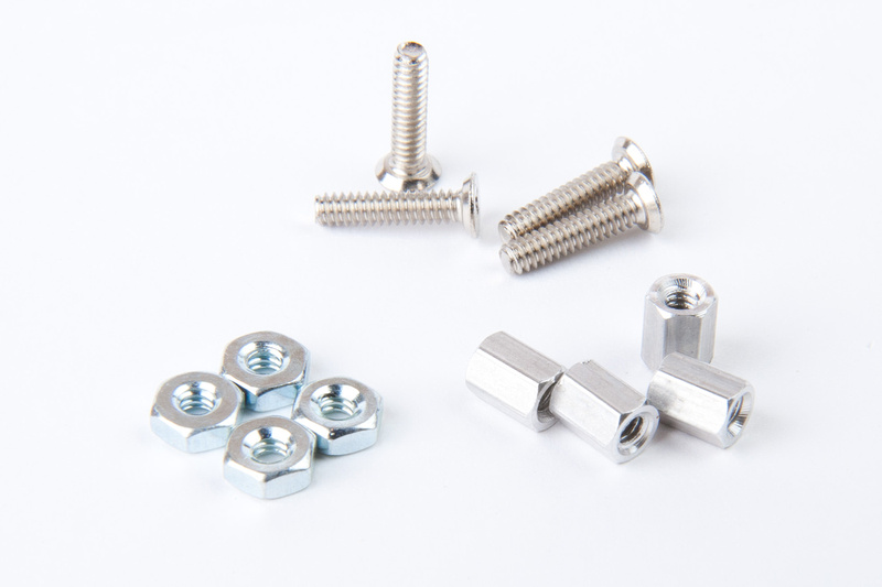
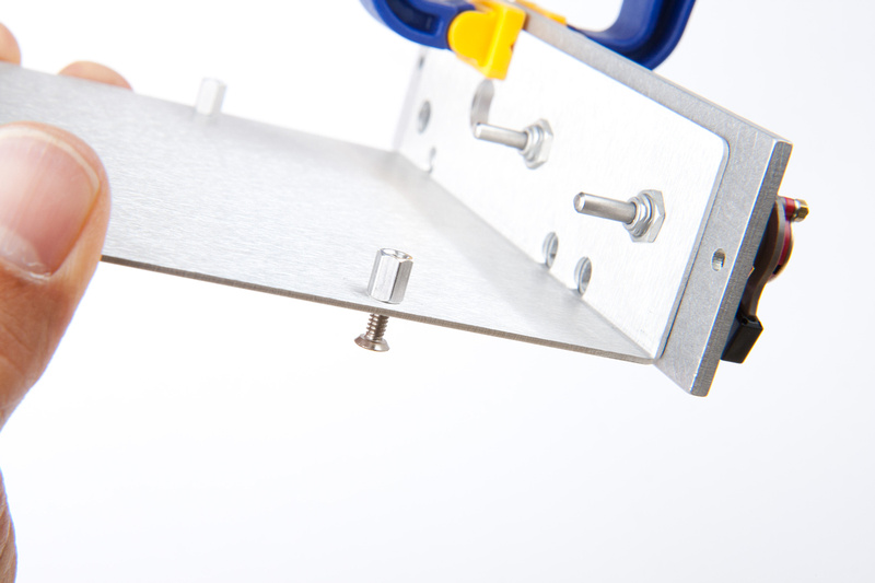
Install standoffs and screws as as pictured below.
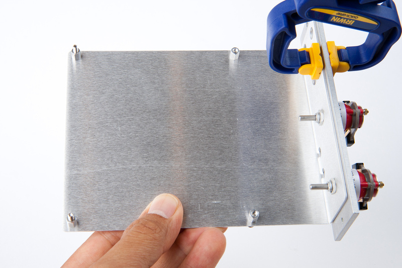
Making sure to leave the front 2 standoffs loose so the screw does not protrude over the top of the standoff.
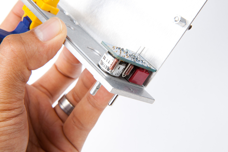
Then, carefully slide the PCB into position.
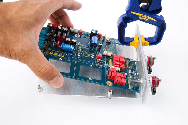
And secure the nuts (without lock washers for now).
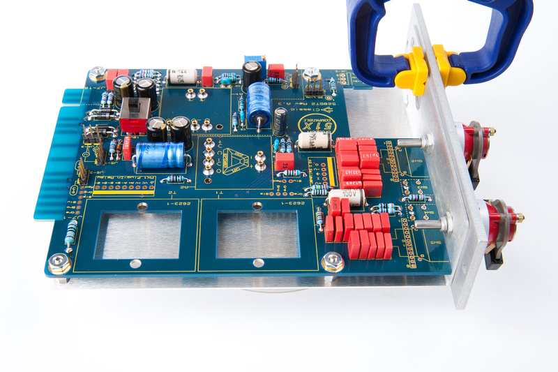
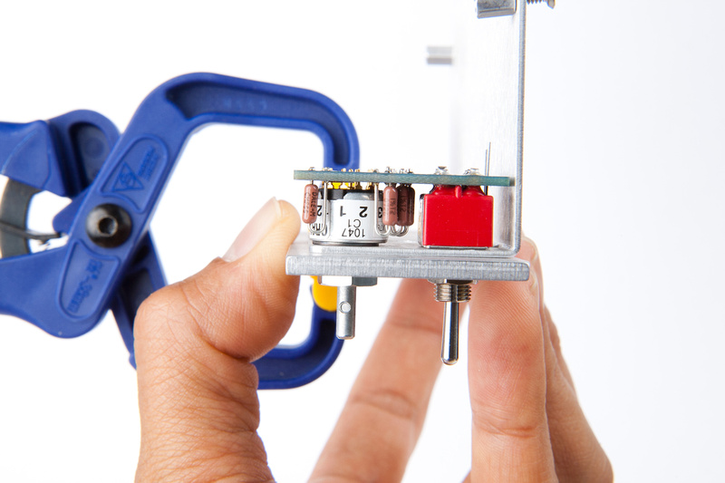
Confirm proper seating of the mini-toggle switches as well as the PCB being precisely aligned with the L-bracket.
And solder the remaining lugs on the mini-toggle switches with the unit assembled.
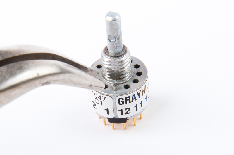
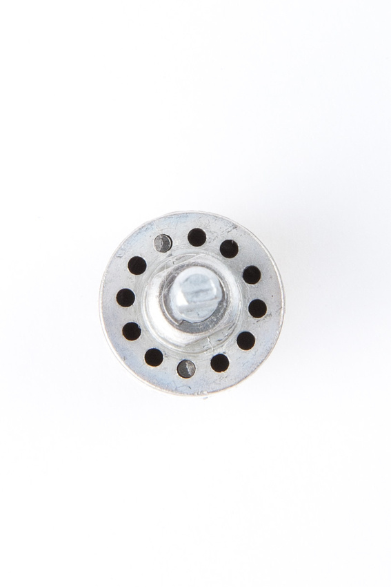
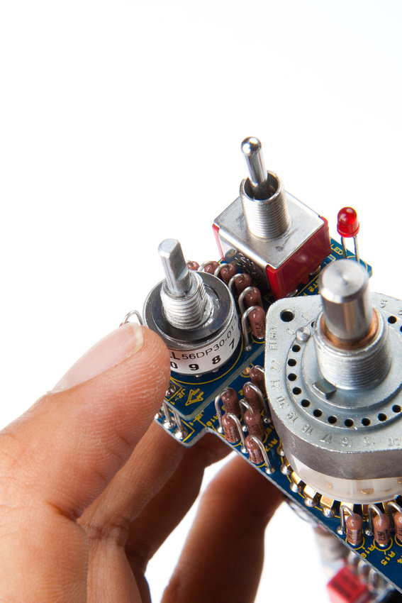
Next, I take a close look at the Grayhill switches. . . this particular kit is an early-run kit, and the position stops on the Grayhill switches are pre-installed. Later versions of the kit will require placing the stop pins as they will utilize a more universal setup on these switches.
It is important to position these switches perpendicular to the PCB, and to facilitate this, jsteiger recommends starting with the inner switch, soldering 2 outer rear lugs first, verifying component alignment, and then soldering the front 2 lugs.
Then, proceed to the outer switch and repeat
After all is aligned, carefully solder all of the remaining lugs. Check for solder bridges as these are pretty narrowly spaced.
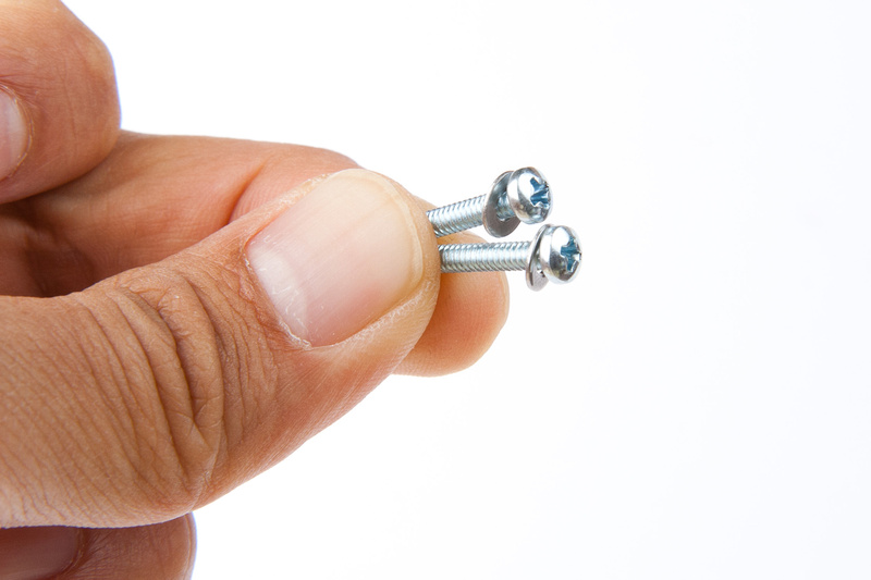
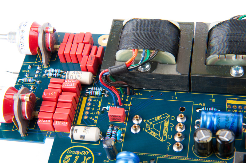
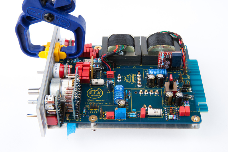
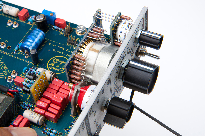
Next up are the 2623-1 transformers.
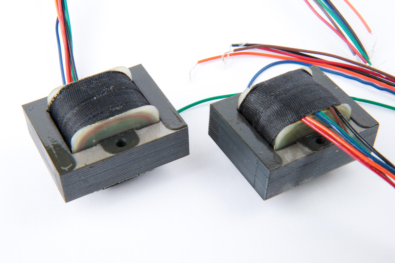
Locate the mounting hardware.
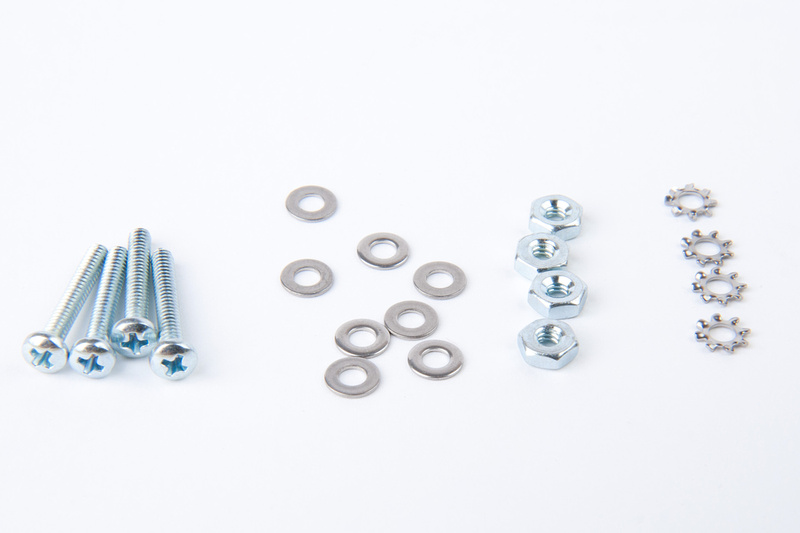
The component sequence for installation is as follows: Screw, flat washer, transformer, flat washer, PCB, lock washer, nut.
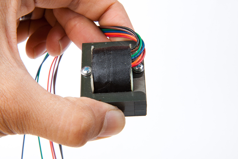
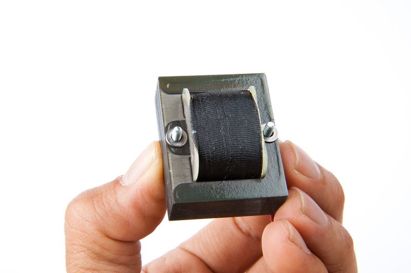
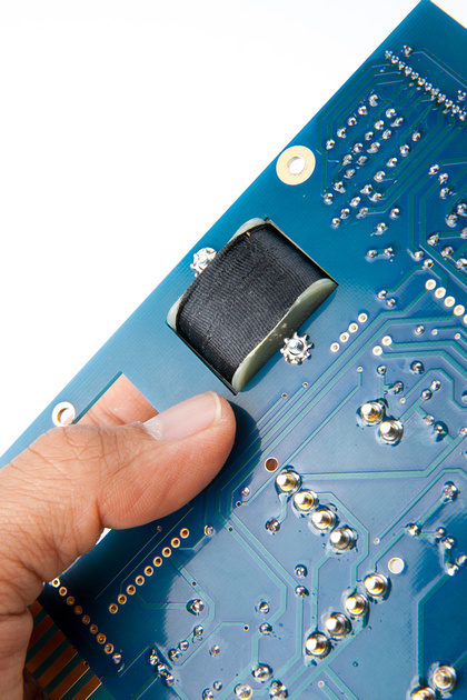
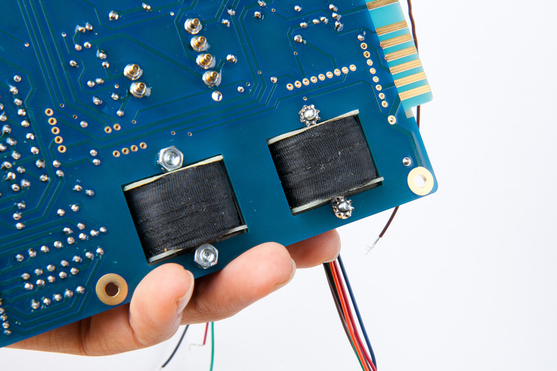
And, transformers are positioned on the PCB.
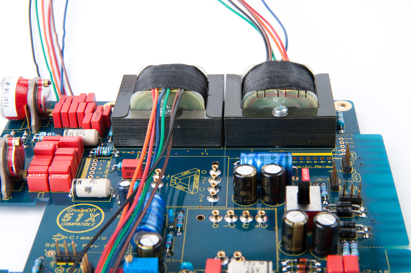
Use short segments of shrink wrap to consolidate the wires and solder to the appropriate locations on the PCB keeping the wire runs short. Be sure to route the wires well clear of the op-amp location.
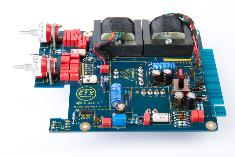
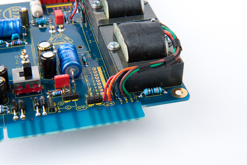
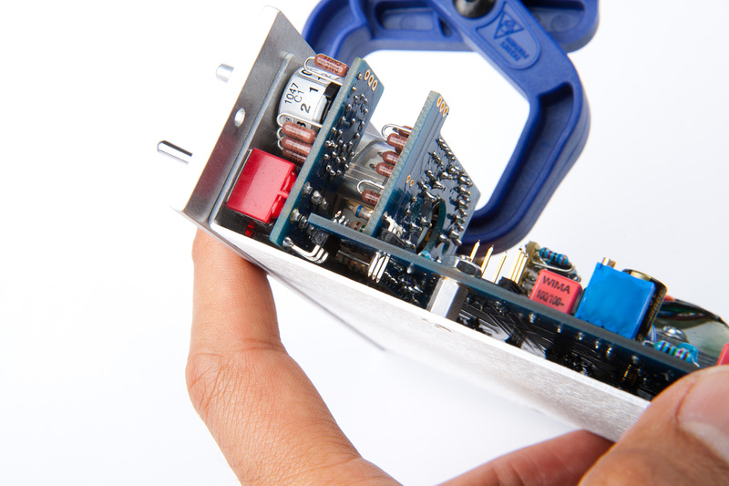
Next, I install the relay sub-board. Make sure the relay board does not short out against the transformer.
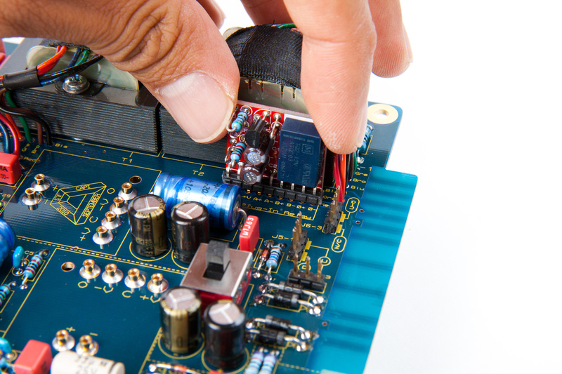
. . .and the discrete follower sub-board.
And, this is where I stopped tonight.
OK. . . last push. I took a moment to pause because the following assembly steps were complex and I wanted to make sure everything was clear in my mind before melting stuff together. After reading the instruction set through a few times, I determined that hilarity would probably ensue especially trying to photograph some of these steps by myself

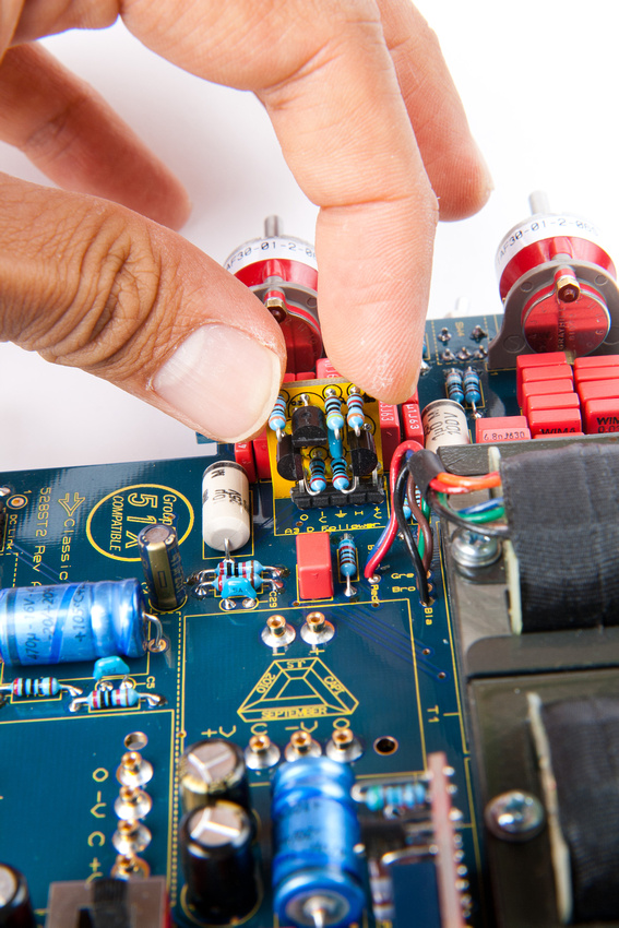
OK. . . next grayhill switch. This is the trim attenuator.
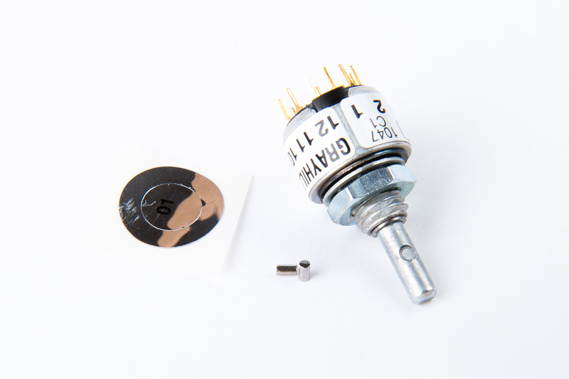
Make sure you don't lose those 2 barely visible pins. We need to insert one between "1" and "12"
. . . and another between "8" and "7"
It'll look something like this from the bird's eye view.
Next, install the stop retainer seal "sticker". Make sure the retainer does not sit on top of the raised center portion.
Next, we temporarily place the switch on the the sub-board without soldering.
We are checking for resistors shorting against the switch's outer metal casing. The gaps are narrow.
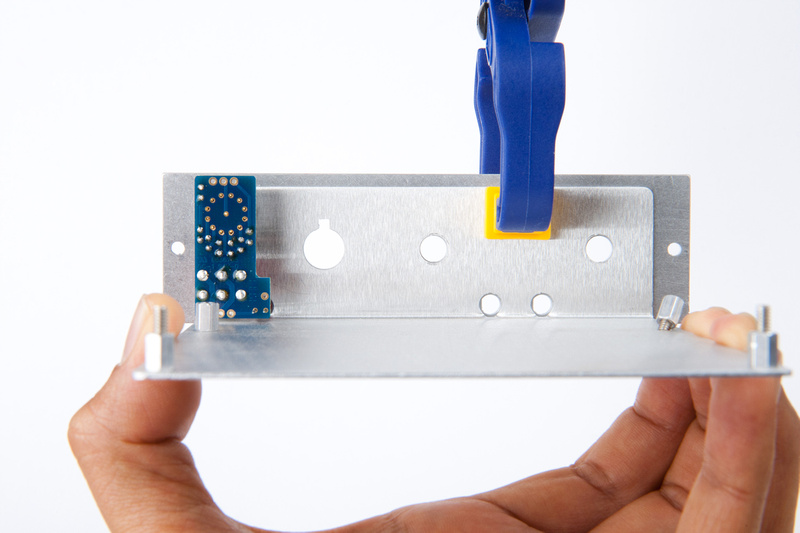
Having established the components do not interfere, we align the L-bracket to the faceplate again and secure with a clamp. Align the hole reveals as perfectly as possible here.
Place the spacer washer on the grayhill switch.
And insert the LED. The small cathode end of the LED should go in the hole the arrow is pointing to.
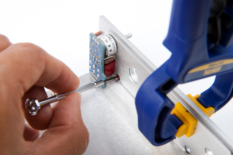
Next, plosition the sub-board (w/ loose grayhill switch and loose LED) and lightly install the nuts.
Fiddle with positioning until the board is perpendicular to the L-bracket and all spaces look even and correct.
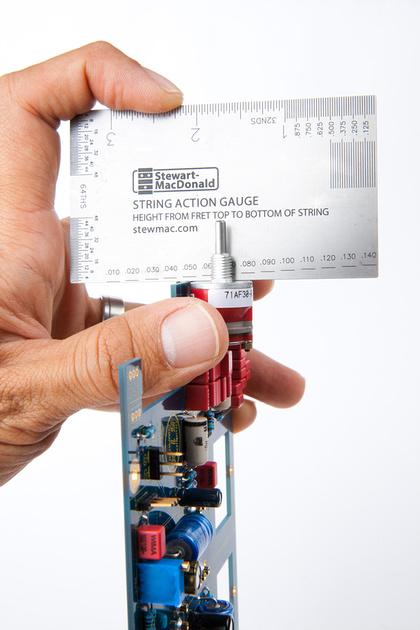
According to the instructions, there should be a .410" gap between the L-bracket and the sub-board.
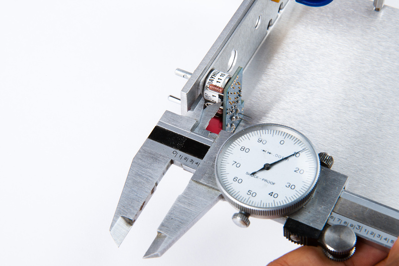
After verifying everything is properly positioned, I tightened the nuts just snug.
Next, push the LED into the faceplate.
This should protrude slightly in the front. Solder the LED in, and trim the leads.
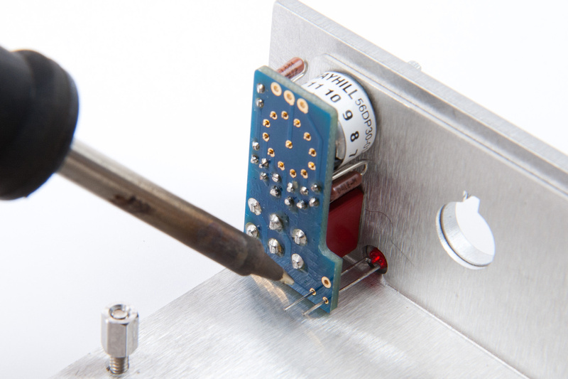
Then, double check alignment and gaps again, and solder the grayhill switch.

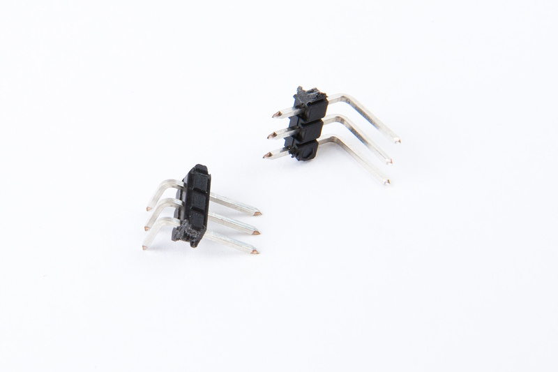
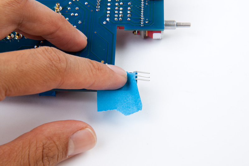
Next, locate the 2 L-headers. There should be a long one and a shorter one.
Place the long one on the back side of the main PCB at J1-3.
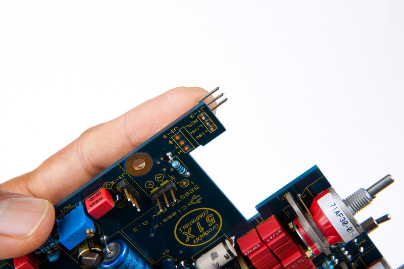
Because we're getting close to that part with the hilarity, I used a little tape to keep this from falling out.
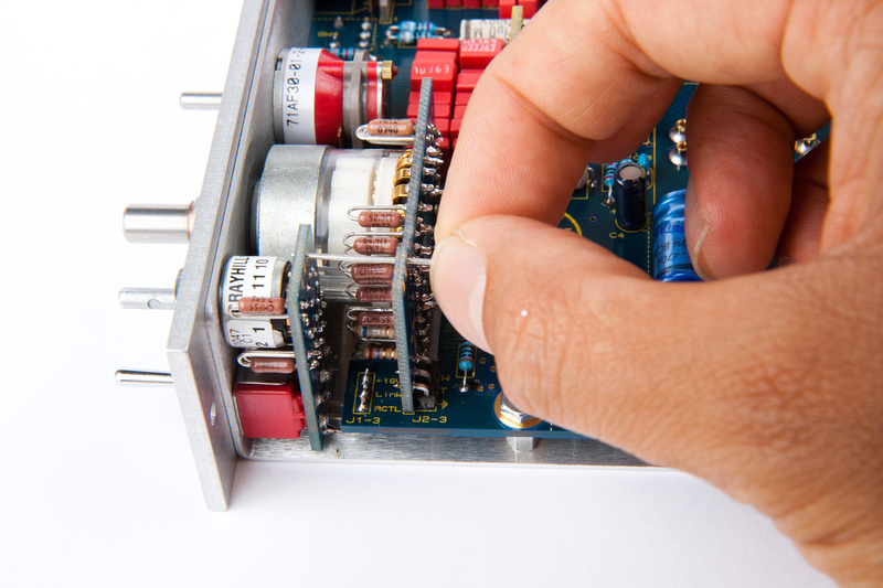
Next, place the shorter L-header on the backside of the main fader sub-board.
Ok. . . here's the hilarious part. This was an unbelievably difficult set of pictures to get

Whew. . . all components are in position.
Next, re-attach the main PCB to the L-bracket.
And, secure the nuts on the front faceplate. Make sure the main fader sub-board is pressed firmly against the main PCB.
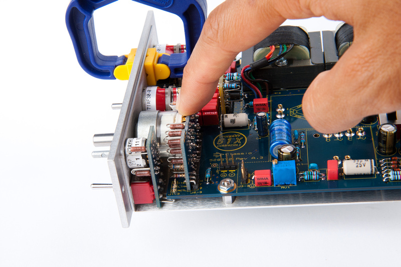
Check component alignment all around to make sure the sub-boards are perpendicular. It doesn't hurt to be very careful at this stage as a mis-step here could cost a lot of time and effort to undo.
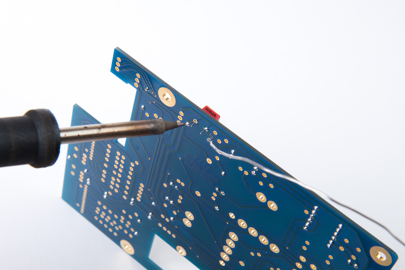
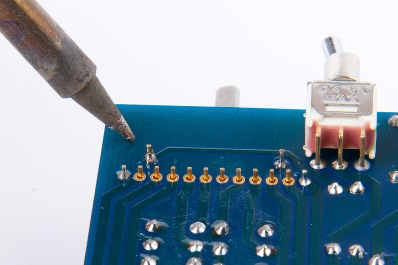
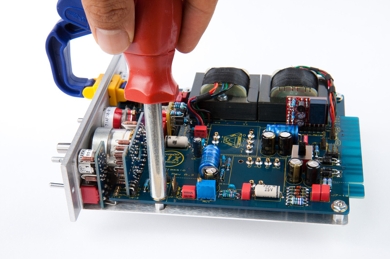
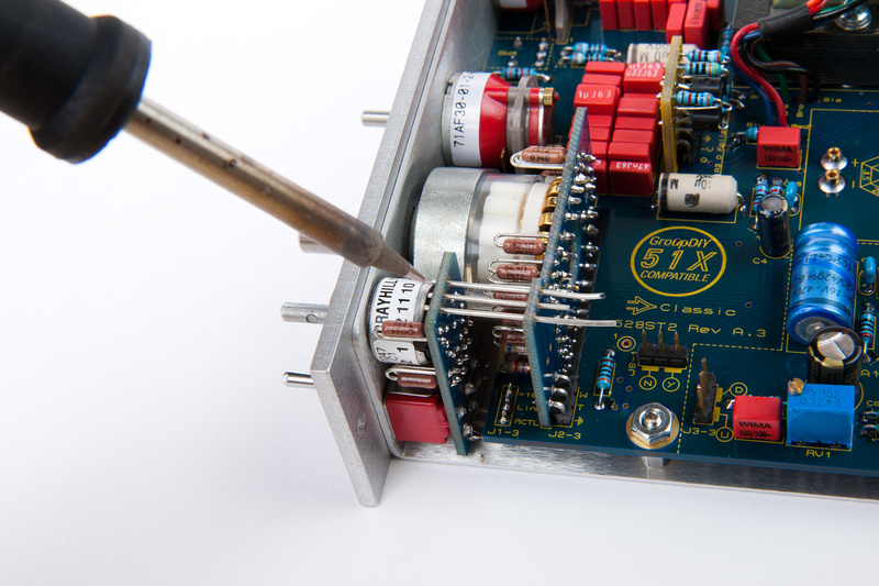
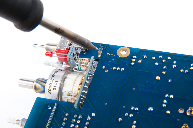
Next, I begin soldering the L-headers.
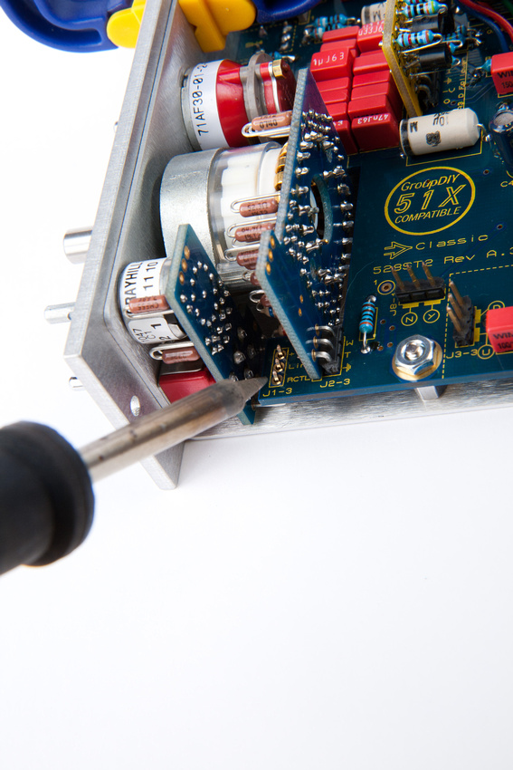
Next, solder from the bottom of the PCB the near lead on the L-brackets. The rest can be completed at a later step.
And, soldered in.
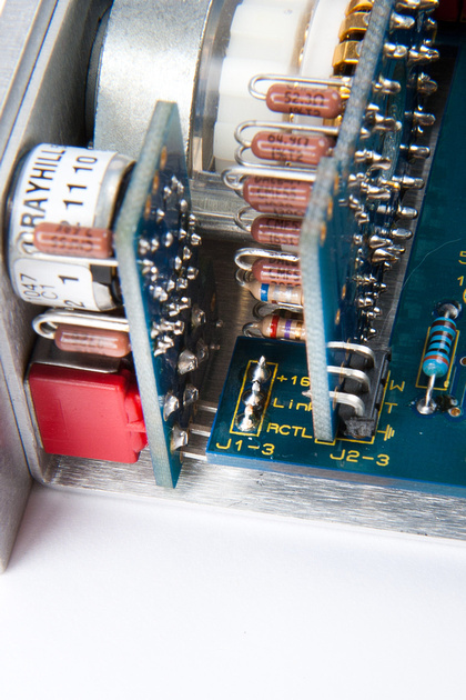
Next, insert leads saved from the large capacitors into these slots.
And solder securely from both sides to make sure there is a solid mechanical connection.
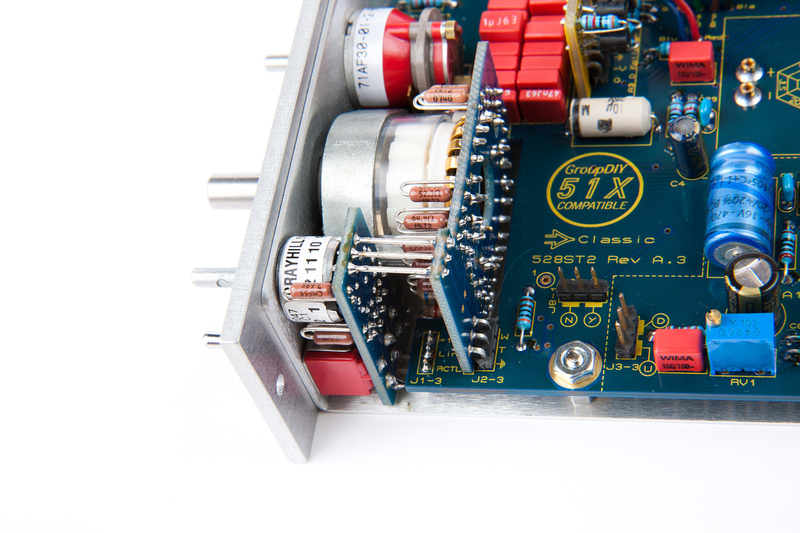
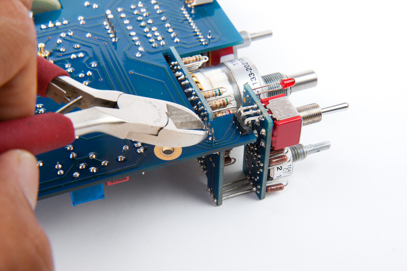
Next, disassemble the unit again, and solder in the L-header leads that were inaccessible in previous steps.
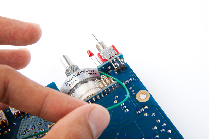
Utilizing a cut-off from one of the transformers, create a ground wire between the trim-switch sub-board and the main PCB.
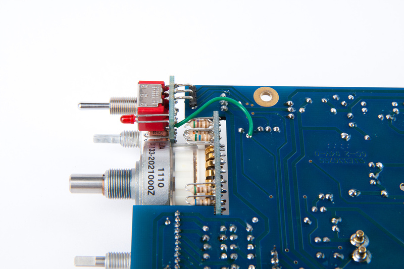
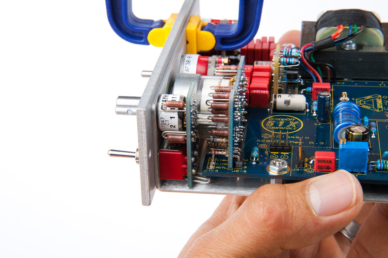
Electronic assembly is complete at this stage. . . next, re-assemble the main PCB to the L-bracket and the faceplate again.
Oh, don't forget about the little spacer on the grayhill trim switch.
This time, upon re-assembly, apply lock washers to the standoffs.
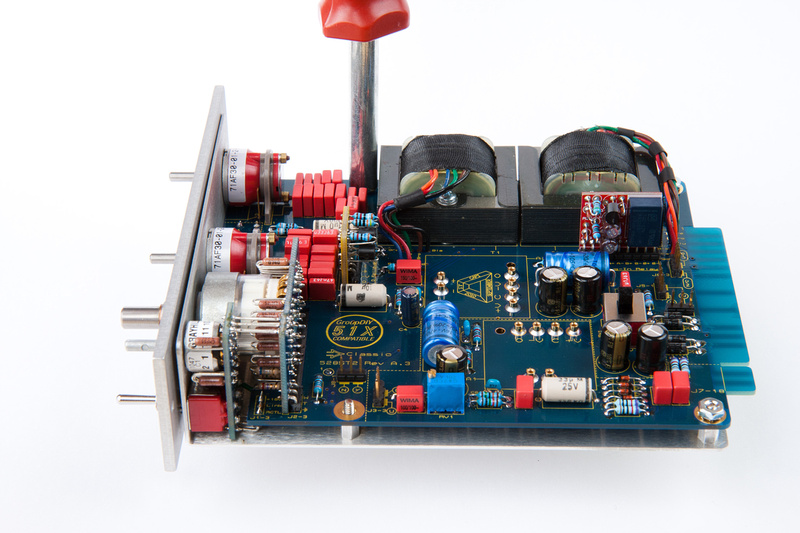
Nuts go on finger tight first. . .and then, using console tape on your sockets to protect the faceplate markings, and snug down the switch nuts with the protected tool.
Poof!
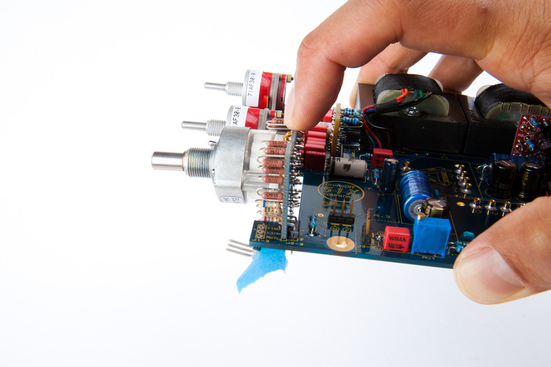
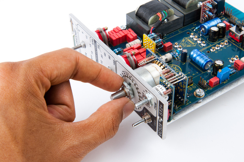
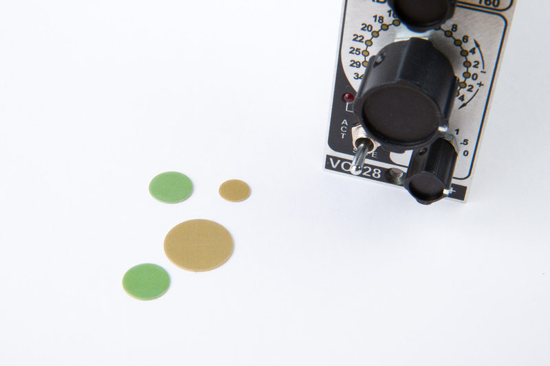
Next, locate the baggies with the knobs.
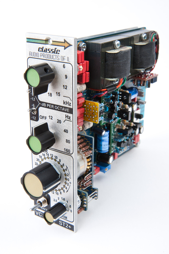
First, install the HPF knob. Use pliers to turn the switch to the 12Hz position and tighten down the knob. This one should be pretty straight forward.
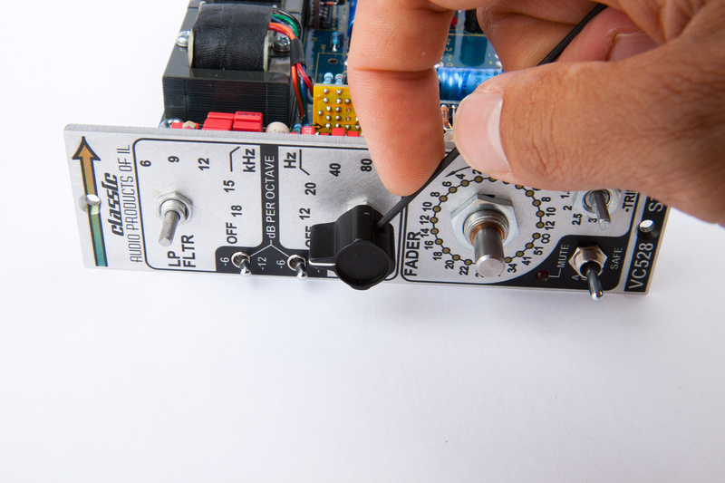
Next, install the LPF knob. This one will be a little trickier because one of the allen screws tightens against the flat portion of the shaft. No problem. . . position the shaft with pliers to 18Khz position. align the knob to point towards the "1" of "18" marking and tighten the allen screw that does not land on the flat portion of the shaft. Then, as the other screw is tightened, the knob will migrate towards center.
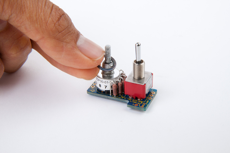
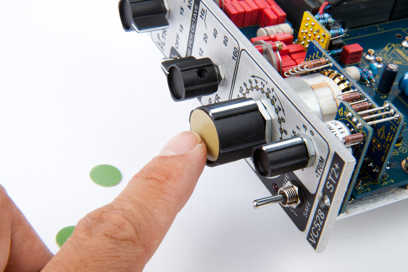
Position the trim twitch shaft to -3db and attach that knob as well.
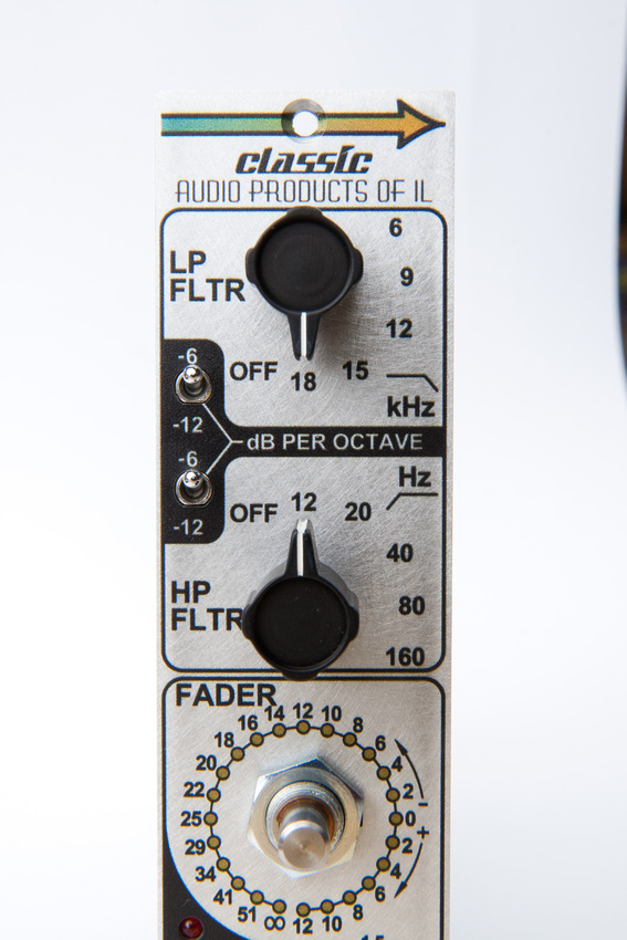
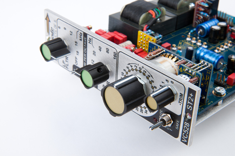
Next, locate the main fader to 0db by observing the copper contact point in the clear window of the switch, and secure the main fader knob.
Sticker time. . .
Next, I take a look at the documentation and decide how I want to configure the 5 jumpers. J6 activates an unbalanced output to pin 3 on the edge connector for a future application. I set that to "NC".
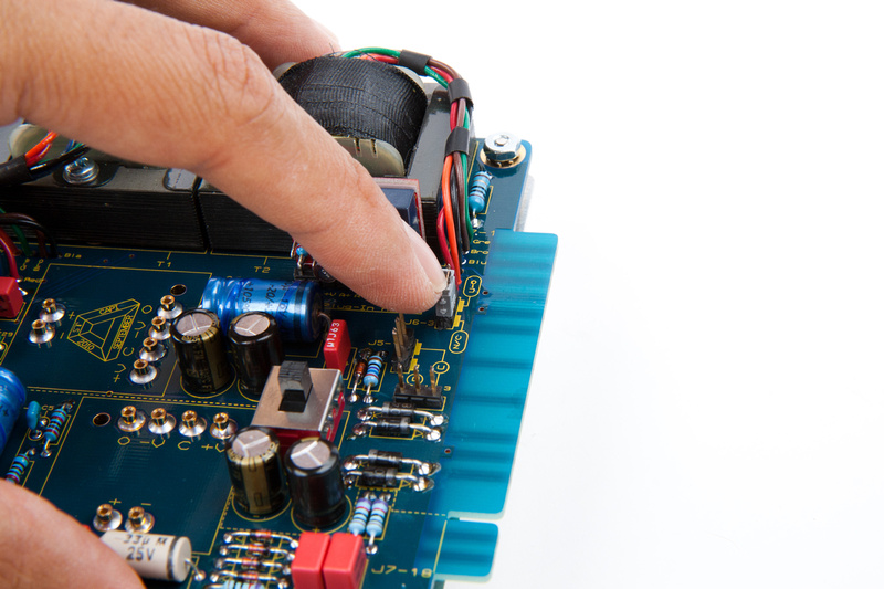
J5-1, J4-3, and J3-3 determine if the discrete receiver stage is inline or bypassed. I opt for "D" or inline. J8-1 is the DC-link option to activate mute logic on pin 6 of the edge connector. I set that to "N" or not-linked since that's how jsteiger ships these stock.
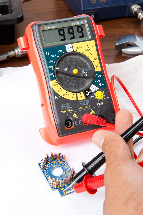
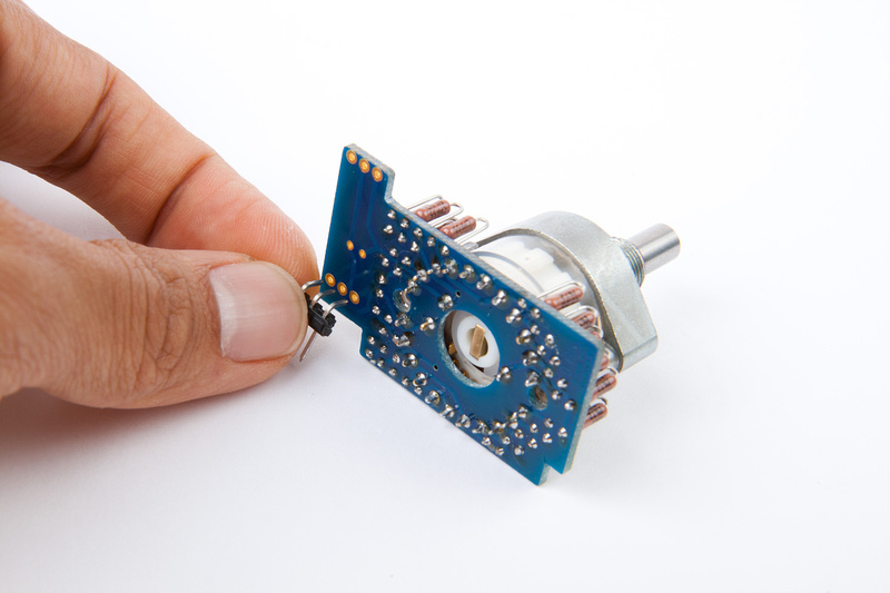
Next, I hook the unit up without opamps installed and see if I read the correct voltages to the op-amps.
All voltages read normal in +-16V as well as +-24V modes.
The red tape indicates this is my bricked GAR2520. . . I haven't been able to figure out what's wrong with it, but it's the first op-amp that goes into every one of my builds because the sockets are bloody stiff the first time pins are inserted, and inevitably, I bend pins or need to apply a lot of pressure to seat the op amp the first time. So, I beat up on my bricked op-amp.
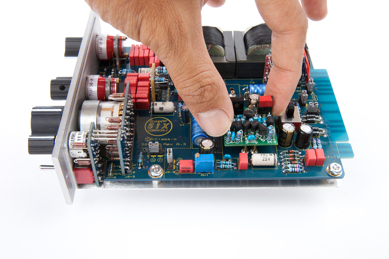
After I insert and remove the bricked op-amp a few times in both sockets, I install a pair of fully functional GAR2520's and make sure to set my voltage to 16V!
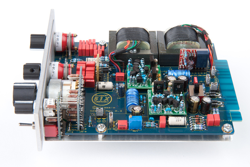
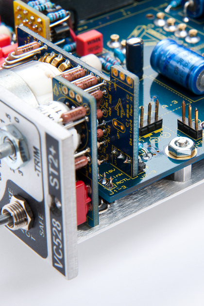
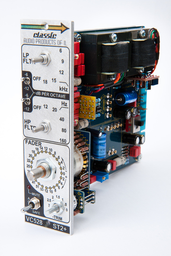
And, there we are. . . assembly is complete on the VC528. . . Humans win!
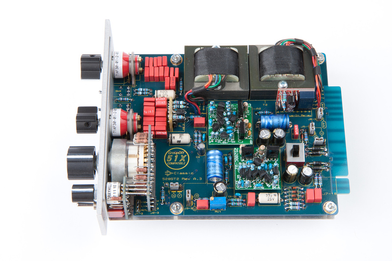
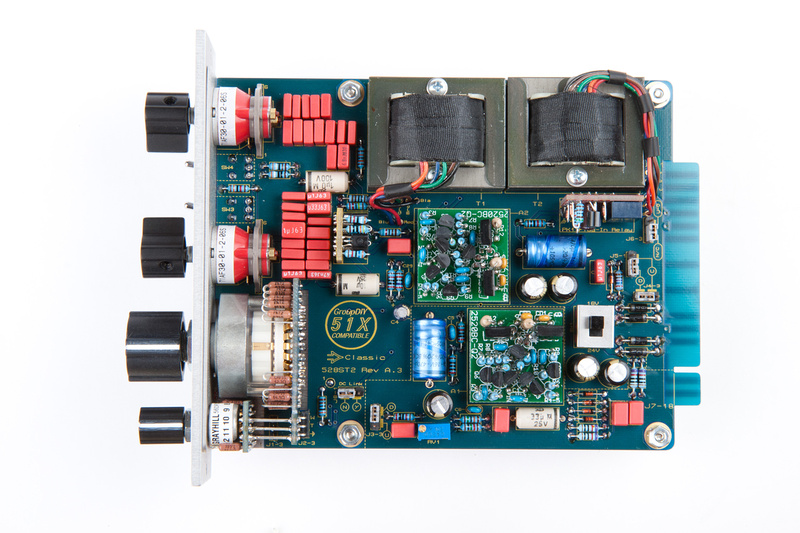
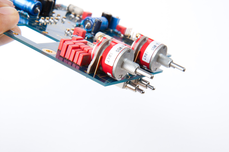
Good things come in pairs. Next, I finished assembly of the matched 2nd channel  I will calibrate them both together, but need to put together 1 more GAR2520 tomorrow to complete it.
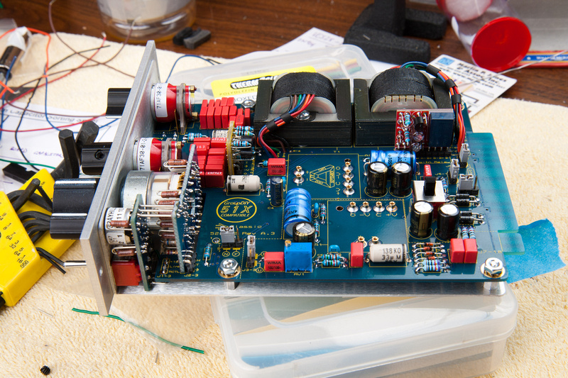
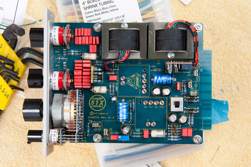
. . . a little more casual with the pics and a much faster build the 2nd time through.
I will calibrate them both together, but need to put together 1 more GAR2520 tomorrow to complete it.. . . a little more casual with the pics and a much faster build the 2nd time through.
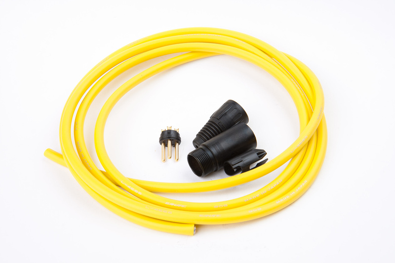
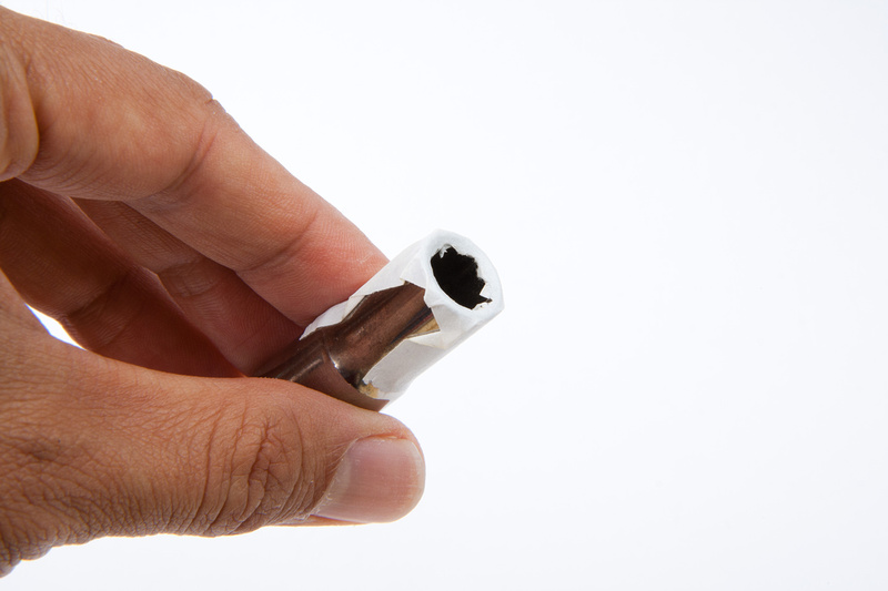
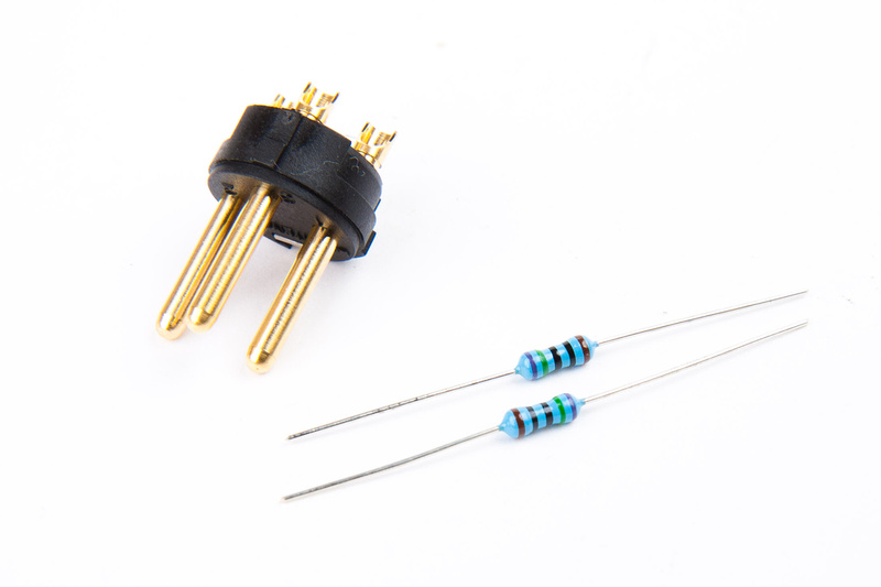
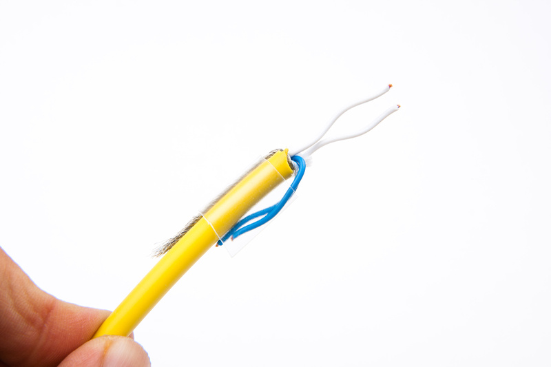
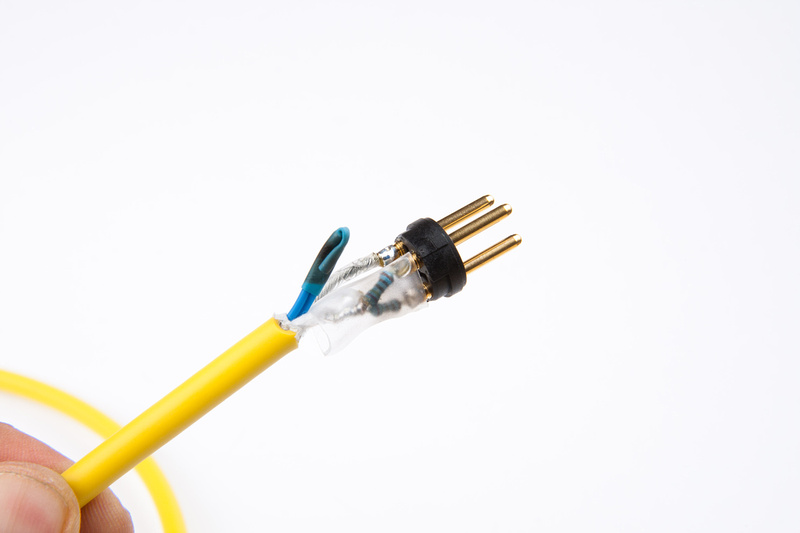
This is the end that will be different from your ordinary mic cable. I am using 2 VERY tightly matched (.1%) resistors. This is important. The value of the resistor can vary. Any value between 100 ohm and 1K ohm will do the job. These are 750 ohm.
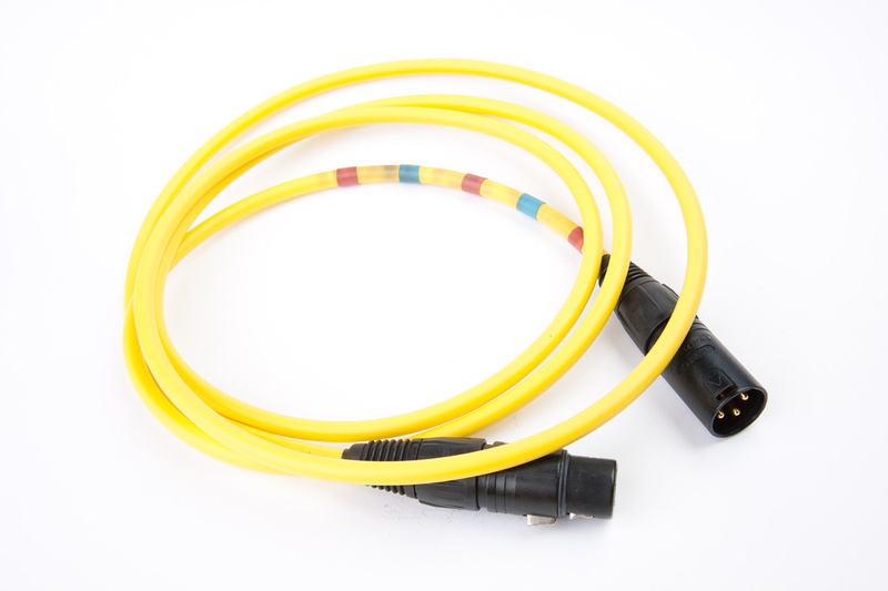
In order to differentiate this cable from the others in the studio, I used some creative shrink tubing. This will certainly be a clue that something is different about this cable and trigger the recollection that this is a calibration cable.

Next, I solder the resistors to pin 2 and 3 of my male XLR connector.
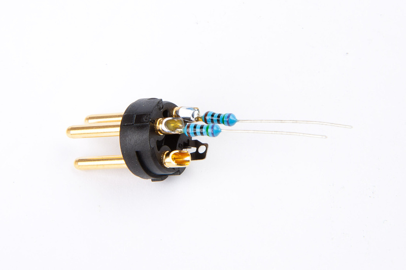
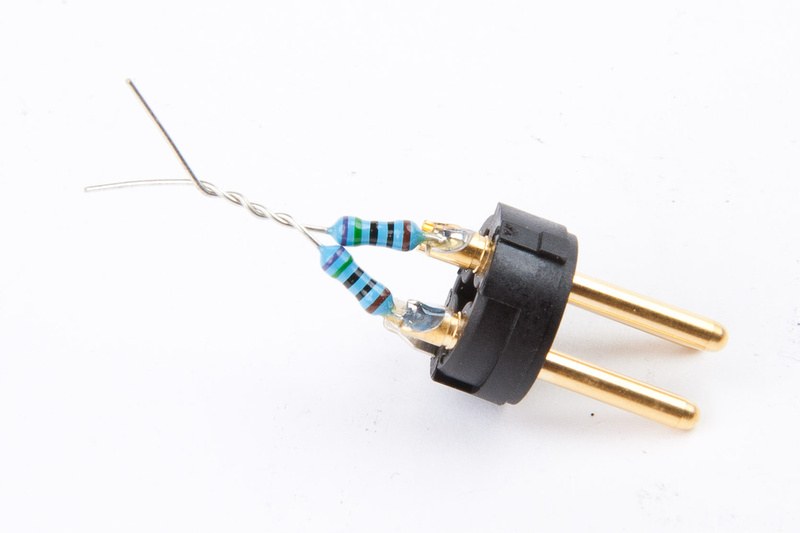
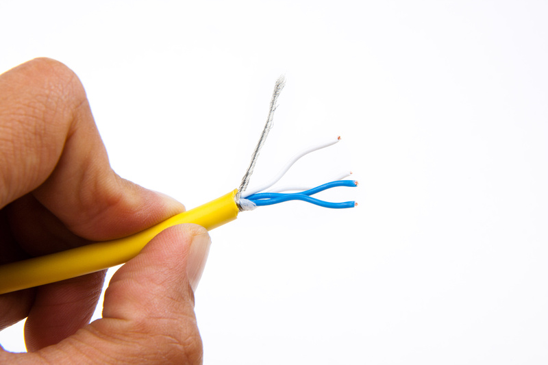
. . .and twist the end together. Pin 2 from the female end will connect to the resistors here.
I'm using Canare L-4E6S cable. . . which is a bit of a pain to work with, but I think is good sounding stuff. Probably completely unnecessary in this application, but this is the only mic cable I had around at the time.
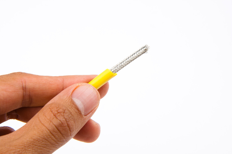
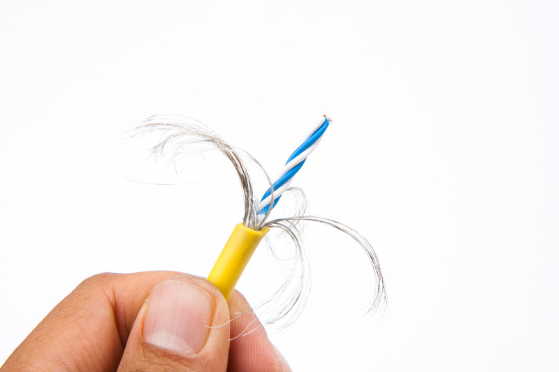
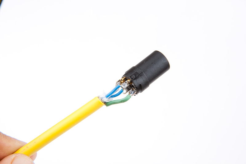
Trying to figure out how to keep the mess from shorting. Not my finest DIY moment, but I think this will work.
The difficult end is done, and the other end wires up as normal.
Calibration cable complete!
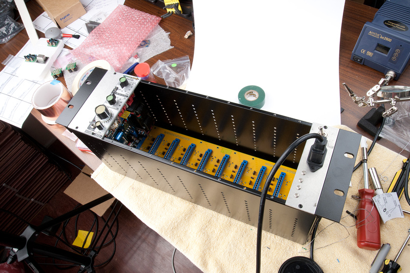
Next, I need to figure out how to get this unit powered up and input/output functioning outside of the rack for calibration. There are many ways to do this, so I thought about it for a while. This is probably something I will need to do with other future modules, so some good tools would help.
First, I thought about just creating a 51X card that is merely a pass-through "umbilical" connector.
Then, I thought about utilizing a little 51X "plug-in" power supply I had rigged up with a JLM powerstation prior to the official powers supply kit being available in the United States.
Luckily, I had purchased some DIY supplies and spare parts to have in my bin for situations like this, and came up with something I thought might do the job more elegantly.
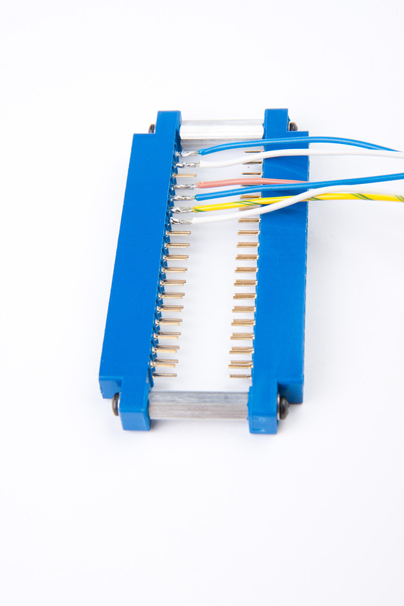
My initial thought was to jumper straight across for an easy build, but then, I realized the modules would have to be inverted from each other to work, and the handling may become awkward.
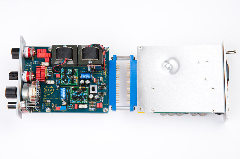
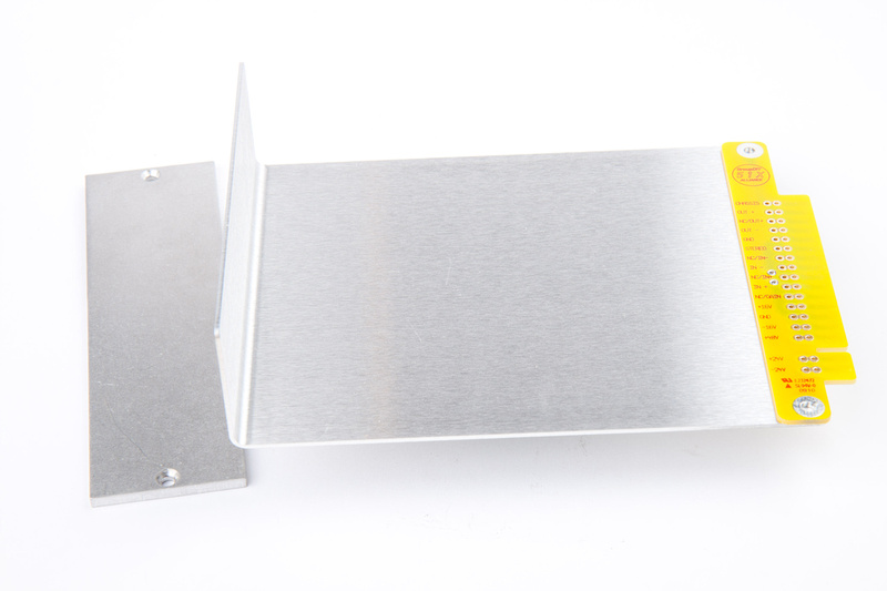
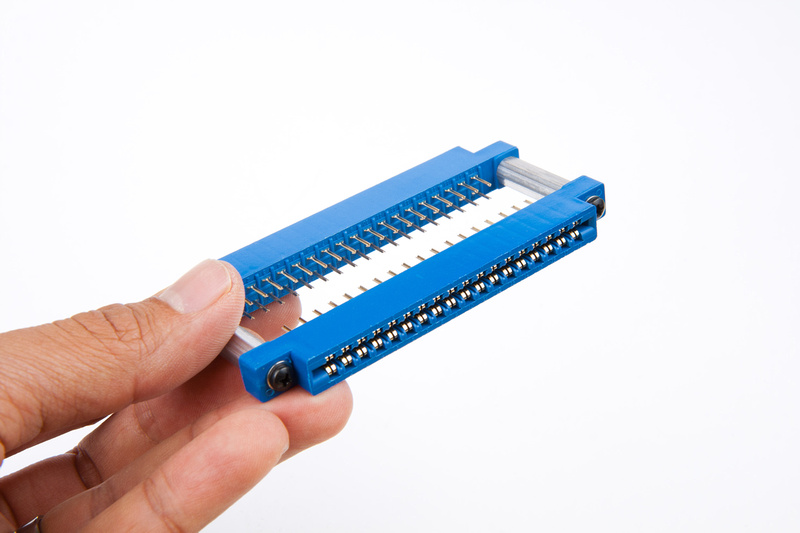
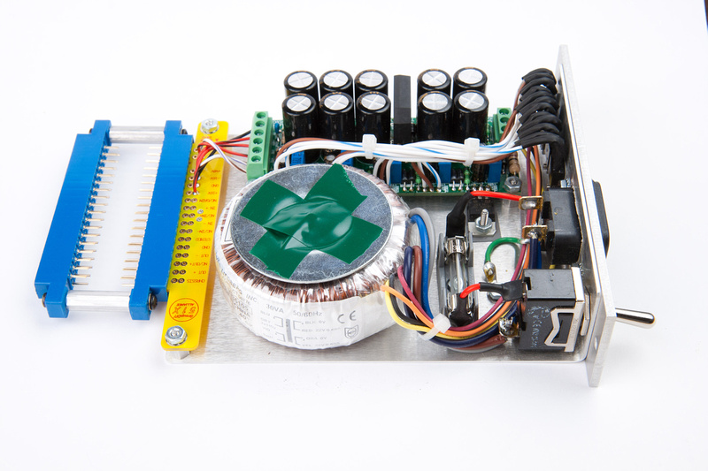
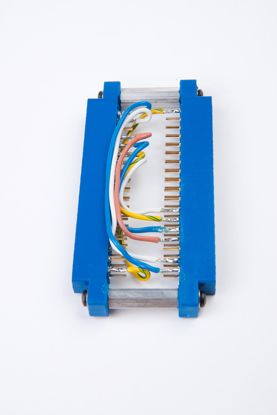
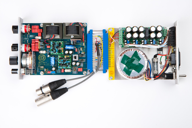
So, I abandoned that idea and decided to wire the adapter so the modules could both orient face up which basically means connecting all wires to the opposite end.
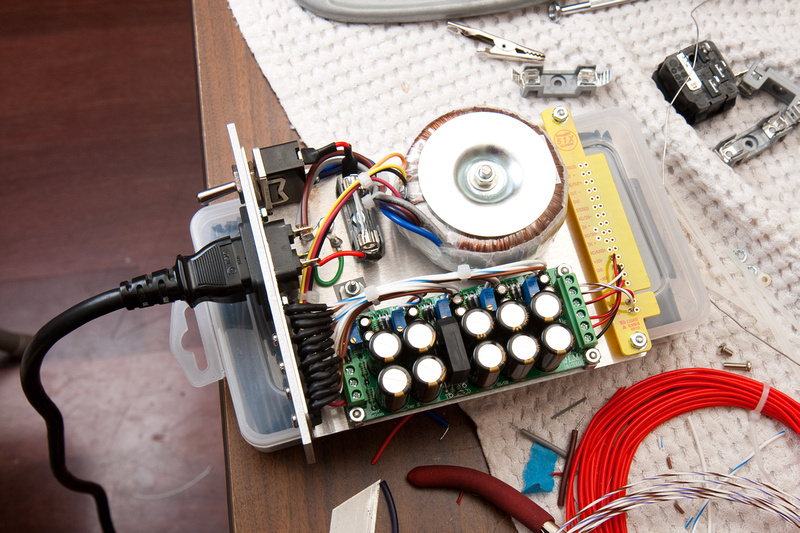
And, this is what I ended up with. . . powersupply goes on the right side, and the VC528 goes on the left side w/ the main input and output connectors spliced in for easy connection.
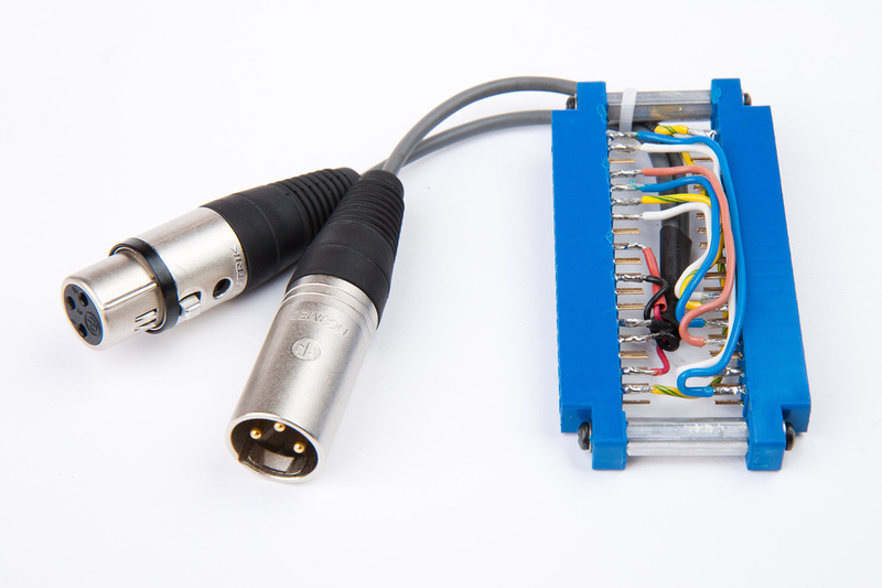
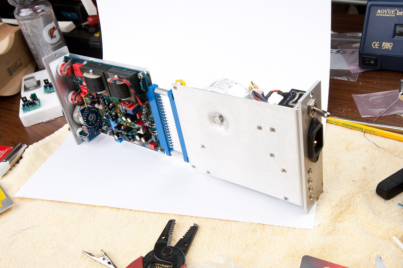
And, all hooked up. . .
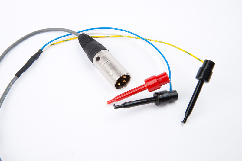
This is looking like it might work for when I bring this into the studio to calibrate. One more small item remained, and that is an XLR cable with test clips on one end to clip onto specific leads on the PCB. Again, digging in my parts bin, I come up with this.
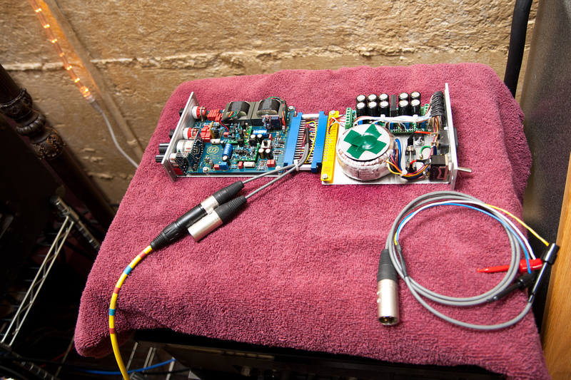
Now, I am really ready to get these VC528's dialed in, and hopefully have some simple tools that I can re-use for calibration and testing on other modules I assemble. Next, I bring the modules into the studio to perform the calibration procedure and hear them for the first time.

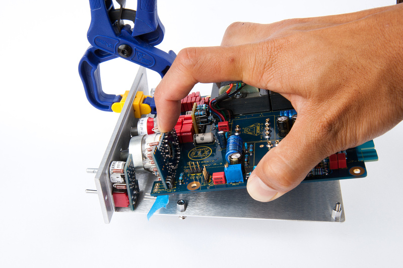
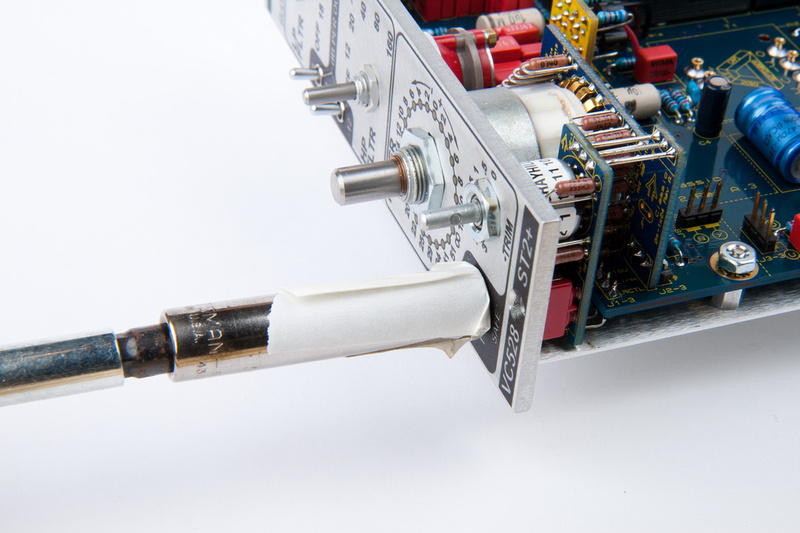
And my tools deployed.
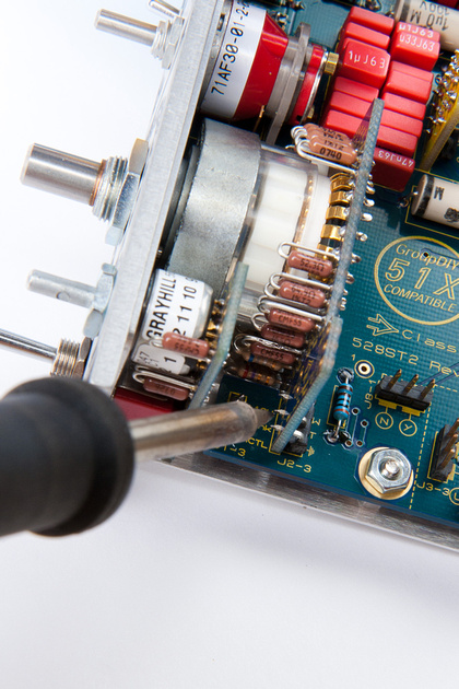
probes placed and adjustments being made. . .
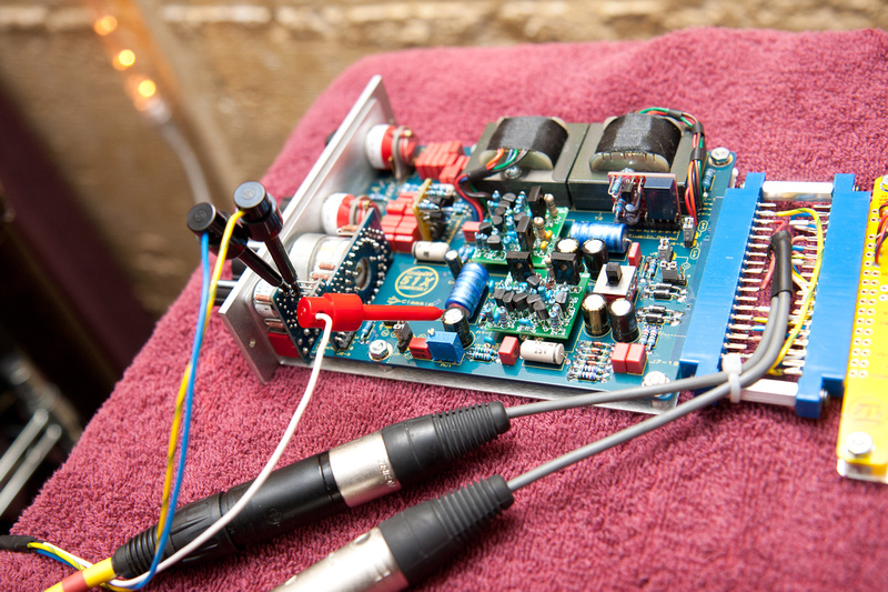
. . . according to the detailed instructions provided, I feed a 400Hz signal to the input through my special cable w/ matched resistors. Then, I output directly into my A/D converter (apogee Rosetta in my case) and monitor the output off of my little clips on the PCB as pictured above on a metering plug-in in Logic (or any other DAW). I turn the trim pot clockwise quite a few turns and then i see the levels drop. Once I find the lowest point, I lock my setting in by painting the trimmer pot with some nail polish.
I'm running Gary's GAR2520's in these VC528's because that was the opamp that jsteiger suggested I run. From reviews of the VC528, it seems the GAR2520's are a great "standard" opamp for these if you are looking for something with some flavor but pretty down the middle for "general use".
The sonics on these units was pretty incredible. There are very few pieces of gear that I would envision using ALL THE TIME, but inserting these onto my main LR mix bus, bumping the level up ~4dB was so awesome I really don't see a reason not to leave it there pretty much forever. Added a bit of weight to the mix, gave me some harmonic dimensionality, and made everything a bit punchier in a very refined way. I do not see audio devices of this pedigree anywhere near the cost of entry.
This was not a unit that I would have sought out on my own, but when Jeff asked me to do some official documentation photos for this project, I looked at the likely applications and said to myself, "This really needs to be a stereo pair." Having played with them for a short test session, I feel very validated in that decision. I have yet to play with these in tracking, but I would encourage fence-sitters to experience these in multiples of 2 especially because Jeff matches many of the critical resistors to .1% on the stereo bundle kits. The likely stereo applications are too numerous IMO to do just 1. The mute linking via pin 6 is also pretty trick.
I hope this in-depth look at the Classic Audio Products VC528 "the missing link" module has been entertaining and informative. It is certainly a module to check out if you get a chance and are feeling adventurous.
I Chunger! I have a pair of vp28 on their way from CAPI. It will be my first time building one of these. My question pertains to clean up of excess flux around the board. I noticed on the VC528 pics there was a bit of flux on the board in the pics. Did you ever clean this up? Does it still function beautifully? Can I get away with not cleaning the vp28 and having it function fine for a long time? I have tried cleaning pcb's in the past and they just seem to get more dirty and have more problems than leaning them alone.
ReplyDeletehey, I'm building my 2nd ML2. I found this older post thread and wanted to comment on how well it was done. Does anyone out there have a schematic of the ML2 or the older ST2? I would like to add it to my documentation on this project. I did trace out the BYP/ACT and relay circuitry but stopped there.
ReplyDeleteLater.
Projects like the VC528 demonstrate the importance of well-designed printed circuit boards, organized component placement, and precise assembly techniques in electronics manufacturing. High-quality PCB design and assembly processes ensure signal integrity, reliability, and long-term performance in audio electronics.
ReplyDeleteIn the broader electronics production landscape, companies specializing in SMT Assembly Poland
also play a significant role by providing professional PCB assembly, testing, and manufacturing support for complex electronic systems used in audio equipment, industrial devices, and other advanced applications.