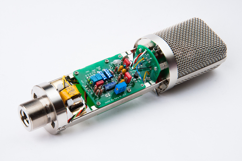
The current AI version of this microphone retails for around $3,200. This build will consist of low-cost unmarked import microphone body that I am now importing at quantity (based on ShuaiYin SYT-5 microphone),

a circuit board designed by poctop available for purchase in the white market section of www.groupdiy.com,
a T13 output transformer wound by Oliver at Tab Funkenwerk,

and a high quality P-K87i capsule sourced from Peluso.

Alternately, tskguy from the groupdiy forum hand makes a beautiful K87 capsule completely in the US at comparable price to the Peluso capsule. The resulting microphone should be uncompromising in sonics but cost less than 1/4 of a new U87 at retail and far less than a new condition vintage U87.
After downloading the project files with schematics and a detailed excel file with the parts list, I used the link which automatically populated a Mouser.com online shopping cart with the required parts for this build. This microphone is a single JFET design that requires circuit optimization around the specific JEFT used. Even with modern component tolerances, these vary pretty widely. It is desireable for the Fairchild 2n3819 JFET specified for this build to select a JFET with low IDSS rating. The range for this particular part is 2ma to 20ma. Of the 10 fairchild 2n3819 jfets I purchased from the BOM, the lowest IDSS was about 10.2ma . I did ordered a pile more of these on Ebay to try and find a lower IDSS copy, and ended up using a 7.5ma IDSS copy for this build. As I understand it the higher IDSS JFETs will yield higher dynamic range before distortion, but the overall output level will be a bit lower than the lower IDSS ones. Anything along the mid-range of the spec should be fine. 8-12ma IDSS. One of the resistors which is commonly replaced by a trimmer pot is selected after the circuit is built to match the characteristics of the specific JFET to properly bias the circuit. This can be done by ear or by using a scope.
To measure the IDSS values of the JFETs I acquired, I used the method described by Matador in the official build thread at the groupdiy forums:
Short gate and source together (pin 1 and pin 2) and connect to the negative side of a 9V battery. My multimeter in current sensing mode is hooked up between the drain (pin 3) and the positive side of the 9V battery and I measure the mA and make note. I found it easy to leave the jfets in their bulk packaging and just write values on the cardboard.

All of my current 40+ JFET's were between 4.4 and 15 mA IDSS with the majority of them being in the 10-13ma range.
Next, according to the build documentation, R18 and R19 need to be matched to .4% and my cheap multimeter is not up to that task. So, I went on google and found a method that uses a wheatstone bridge.
I'm not sure how actually accurate the method is, but I was certainly able to make differentiations between my 40 1% resistors. Which is better than I was able to accomplish by just using my meter directly.

Utilizing the 1st half of the described methodology, I was able to find 7 matching pairs to the limits of my meter's sensitivity. Hopefully these are within .4%

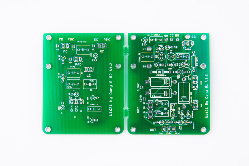
Note, there are 2 versions of PCB's available for this project. There is a smaller tapered version that fits into a number of smaller bodied Chinese donor microphones. The one I am using for this build is the larger variant designed specifically for the modified SYT-5 body. The first step is to separate the 2 PCB's.

Since I started building mics, and read about high impedance sections of the circuit needing to be clean of solder flux, I've been super-obsessive about cleaning everything. I found some 91% isopropyl alcohol at the convenience store and it's been working well for me for cleaning solder flux. Mechanical scrubbing with a toothbrush and generous use of the alcohol to dissolve and flow the flux off of the pcb works brilliantly to clean the boards.

The first of many dips into the cleaning solution.

I select one of my newly matched pairs of resistors and begin populating.

I use the smallest screwdriver shaft that I have to help bend the resistor leads nicely.

And, I start to populate the boards referring back the BOM often. I did not sort all of my components onto a piece of paper like I usually do because all of my parts were still in their Mouser Electronic baggies and clearly labelled.

Next, I move to the capacitors. The tantalum caps have polarity, so heed the markings even though they are small. I am building per the "original" options on the BOM, so I will be using tantalum and polystyrene capacitors.


The electrolytics also have polarity, so make sure you get the "+" and "-" sides correct.

The teflon isolation pin is press-fit into the provided hole.

and, most items are populated with the exception of the polystyrene capacitors. I read that those are sensitive to alcohol, so I wanted to clean the boards thoroughly before I install those.

Note, the "Source" leg of the JFET is soldered to the teflon isloating pin and not to the through hole on the PCB.

Next, I pull some 24 AWG silver teflon wire that I keep around for projects. These wires can be purchased at reasonable lengths and in a variety of colors on Ebay.

. . . and I connect my wires for switches (Low Cut, Pad, and Pattern).

Before the polystyrene capacitors go in, I clean my PCB with alcohol and a toothbrush.

Next, I trim the pin of the teflon isolator so the PCB's will clear each other when mounted.

. . . and install jumper wires to connect the 2 pcb's together.

Every time I solder, I leave flux on the PCB, so I clean whenever possible.

And styrene capacitors are populated.

And, at this point, I complete the connections between the 2 pcb's. A to AA, B to BB, C to CC, and G to GG. Note, G attaches to the teflon isolated pin.

The large PCB leaves provision for separate installation of the bias potentiometer. Unfortunately, the original BOM had a trim pot spec'd that had staggered leg configuration instead of straight like on the PCB. I simply bend the center pin a little bit to fit the straight hole pattern.

with such a large diamter microphone body, I doubt it will be a problem, but I install the trim pot at an angle to help with component clearance near the edge of the PCB.

And, at this point, I make a quick check just to see where everything will sit inside the microphone's frame rails.

Next, I pull a switch mounting pcb which I have a supply of in stock from poctop as well as the 3 switches provided in the microphone body kit. 2 of the switchs are on-on type and one of them is on-off-on for the pattern adjustment.

I solder a single pin on each of the switches to begin so I can make small adjustments and line them up perfectly with the screen printing on the front side.

After confirming alignment, I solder the remaining legs and keep my microphone outer tube handy because I will refer to the screen print markings on the body to make sure I wire up the switches properly.

And, I take the opportunity to thoroughly scrub my switch PCB with alcohol.

And, I begin wiring the switches checking carefully to make sure my switching corresponds to the markings on my particular microphone body.

A quick test fit confirms my wire lengths are reasonable. I want the runs to be relatively short, but also want to be able to move the boards a bit for diagnostics and repair in the future.

All 3 switches are now wired up.


Next, I pull some hardware. . . these are 5mm and 12mm M2 screws, 1/4 inch 4/40 standoffs (these are not quite "proper" but are what I had), and some washers.

The 4 short M2 screws attach the PCB's to the frame rails. I made sure to leave enough wire slack to be able to remove and work on each PCB if necessary to change components.
Washers and spacers go in to install the switch PCB.


This body was not originally designed for 3 switches. The reason I'm using washers is to make this screw clearance under the pattern switch (that was not in the mic's original oem layout).

Two solutions are possible here. . . well, two easy ones and one harder one. The easiest is the one depicted here which is add a washer to the 1/4" standoffs to clear the screw. The second easiest is bevel the hole on the headbasket base plate and use a flat head washer in this position. The third would be to drill 2 new holes to mount the headbasket that do not interfere with the switch and tap those holes.
Some people have requested detailed photos of the Peluso P-K87i capsule, so here we go.

Note, the screw on the front edge of the capsule. . . the Peluso capsule can be a little bit confusing to wire up. Although it seems that front screw on the capsule edge would be the front side backplate screw, a trip around the capsule with a multimeter will reveal that it is in fact the REAR backplate terminal and is electrically isolated from the front backplate. Before final hookup of this capsule play around with it on your meter and make sure you understand which connection is the front backplate and which one is the rear backplate. In this picture, the top yellow wire is the front capsule terminal. The black wire is the back side backplate terminal. The front backplate terminal (blue wire in my case) will be screwed into the front backplate when we install the capsule onto the saddle.

The capsule mount that is included with this mic body is designed for K67 installation and only has mounting holes along one backplate so I need to drill one mount hole manually onto the capsule mount.

It's not the cleanest job because i had to enlarge the hole because I originally drilled it in the wrong spot. Ugly, but it'll still work.

One note about the capsule mount, it does sit a bit low in the headbasket, but there is an easy solution. The screw thread is M3, and a standard male to female M3 standoff at about 6mm length can be mounted under the capsule mount and put the capsule right where it needs to be higher in the headbasket. Easy peasy. I'll put one on my next order and demonstrate.
The Peluso capsule is supplied with wire tabs, screws, and washers. I use 30awg silver teflon wire to make a backplane connector.

Next, I install the capsule and thread the wires through the nice pathways provided. I quite like this capsule mount because the height can be easily adjusted and the base shape is curved.


Next, up is the 3 pin XLR insert for the microphone. These bodies are supplied with 3 pin and 7 pin xlr inserts.


The insert secures to the microphone body via a set screw that presses tightly outward to the body when twisted in the reverse direction.

The build could be wired for a cleaner look with a shorter minimum length run of wire, but knowing me, I will have to get back into the PCB to make an adjustment or a correction at some point, so I leave enough slack in the line for future repairs, but not so much that it's overly ugly. . . just borderline-moderate ugly.

HAa ha!. . . right on cue, the Hakko 808 comes out and I'm swapping components on the pcb. What ended up happening is I made a measuring mistake because I was measuring from the gate instead of the drain with my scope as I tried to bias the FET. It is very important to measure from the drain. Because I thought I had a circuit error and could not bias the FET, I started diagnostics and made a component swap that was not necessary.
My voltages were good at the zener (23.6v) so reading through the thread, I replaced R14 (10K) with a pot. Note, all of this was not necessary because I was silly and measuring from the wrong spot.

But, the extra slack in the xlr cable made repairs and changes much easier.

R14 replaced with a pot set to 10K (original value) to start.

I adjusted R14 for a 3V drop across R14 according to diagnostic procedures outlined by Matador on the groupdiy official build thread.
That was when I realized I should go look at the spec sheet for the FET and figure out if I was measuring from the gate (center pin) instead of the drain (outside leg). . . and felt kindof silly. Anyways, here is the correct spot to inject signal (without the capsule connected). The is at R6 which is installed backwards from the silk screening per the build instructions.

And the correct spot to connect the scope to measure at the JFET's drain.

And, measuring from the drain, I was able to easily adjust the bias pot for symmetrical clipping.

And for this FET in this mic, the drain voltage was 11.04V in this configuration.

Next, I solder in my capsule connections. When installing the capsule, I was sure to remember where the front and rear connections are.

And after some thought, I removed the pot at R14 because the build was executed correctly to begin with. Just for kicks, I measured its final value of the trimmer pot at 18K after it was removed. This was set to get a 3V drop across R14. The stock value 10K yielded less of a drop, but I figured why mess with the circuit if it's working as originally spec'd. I had to disconnect the capsule, insert signal again, and re-bias the FET with the original R14 back in, but since I was monkeying around inside the mic already, it wasn't too bad.
Next, I used some zip ties to attach the T13 transformer. I could not make heads or tails of the silkscreen letter designations, so digging through the official build thread, I came across this image that Wave posted. Please note this diagram is incorrect for my T13 transformers as a large number of them were shipped with the yellow and black wires reversed.

Because a large number of T13's were shipped with wire markings reversed from the spec sheet, I checked my transformer and it read about 21R on the yellow side and about 436R on the black side, so mine was reversed. The higher resistance side (yellow in my case) should go towards the capsule side and the lower resistance side (black in my case) should go to the output xlr.
I didn't want to mess up my polarities so I tried following the diagram and reversing the colors since I don't have the foggiest idea what the silk-screened letter indications on the transformer pads mean.
so, with the transformer in the same orientation as the picture, the proper wiring for my transformer is:
Left side black --> RT
Left side yellow --> WS
Right side black --> SW
Right side yellow --> BL


Once the transformer was installed, I proceeded to take beauty shots of the microphone interior because I thought I was done.

. .. and after my nice photo session of my "final" build, I discovered that the tube would not fit over the ziptie that held the transformer in place. . . DOH! And I was so proud of my 3 zip tie solution.

After getting over my distraught, I headed to the local hardware store and found some small pieces of brass bar stock. I bought a thick one that ended up being too tough to hand bend with pliers and a thinner one that proved to be a bit more manageable.

A bit of creative bending with needle nose pliers, and I create a little recess to keep the transformer centered. Blue painter's tape somewhat protects the brass surface from tool marks. . . kindof.

And, we make our outside bends.

I use my fret cutters to shear through the brass stock, and it works pretty well and I have a fair amount of control and precision with my cut placement.

I leave the ends long, remove the base of the microhpone frame and determine my final cut points to make an exact fit.

Ends are cut to length.

A test fitting reveals that my tension fit is quite exact and sturdy. I will not have to drill screw holes into the frame rails to support this.

Next, I make a few notches in the bracket to retain the zip ties that I will use to mount the transformer.

I position the bracket in its final location and use two small pieces of self-adhesive foam.

The double sided adhesive on the foam probably would have been fine for mounting the transformer, but I did not want to "stick" the transformer to the bracket just in case I mucked something else up inside the microphone and I would need to go back into it for repairs, so I found some very think foam and stuck those on top of the adhesive strips.

Two zip ties secure the transformer hopefully for the final time.

Alright! Humans win. Time to take some more beauty shots of the completed microphone internals.


Next, the cover goes on. . . and "Check, check, 1-2, 1-2, 1, 2, 3?"

And the U87 vintage circuit clone is complete. This microphone is a fairly straight forward build with a scope being optimal for setting proper JFET bias, but a method for accomplishing this fairly accurately by ear is provided in the build thread. Total cost for the project is also pretty reasonable at around $560.00 considering the parts used were all of premium quality.
UPDATE:
I'd like to share a quick little mod to the specific capsule mount that's provided with this body. The design of this cheap mount is growing on me a bit because it's really easily and cleanly adjustable for height. Originally, I was a bit bummed that the capsule sits pretty low in the headbasket, but because it is low, you can use a standoff of whatever height you decide to finely tune the capsule height and experiment with it non-destructively.
Here, I will be using a 6mm height M3 threaded standoff to raise the position of the capsule.

First step is to remove the headbasket to reveal the capsule.

Next, carefully remove the capsule and saddle. It's strongly advised to not do this with a camera in one hand because the capsule is delicate!

With the saddle removed, we can easily install our standoff to raise the post height by 6mm.

And, reinstall the saddle and capsule.

Humans win!


I think the capsule height can go up another 2mm so an 8mm standoff can be used here to get the capsule position proportionally a bit closer to the original U87 position, but other variables may play a bigger role in sonic effects at this point like the headbasket being generally bigger than the original as well as the different meshing specs. I like this simple mod a lot. It looks like the capsule is where it should be.
This comment has been removed by the author.
ReplyDeleteAwesome job!!
ReplyDeleteHave you noticied a so big difference before and after modding?
Hi, there was no "original" mic to mod. This is a new ground-up build on a vintage circuit pcb.
ReplyDeleteWhen you Bias the Fet and put the signal through R6, what signal do you apply? a sinusoid at 2V? or the 48V.
DeleteThanks
Wow, just wish I could build one as well, the thing is I have no clue as to half of the stuff you talked about. Have you compared it to a u87? How does it sound?
ReplyDeleteIt sounds pretty close to the vintage the U87. Mine has a bit more top end and is perhaps a bit stiffer than a vintage one, but the caps have not broken in. The additional air and top end could also be on account of the more open headbasket mesh as well as the Peluso capsule. tskguy's handmade K87 capsule is tuned a bit smoother. I will post audio samples soon.
ReplyDeleteMr Ferreira, You could build one.
ReplyDeleteIf you have the ability to use a soldering iron and can follow instructions Your half way there.
Ok, I used to solder for a living repairing tv's and video recorders years ago, but even so...Chunger's article is top notch.
I did it, you can too. I am so impressed with this Mic I cant say enough about how much it blows my old mic away.
Ian
It appears in the picture that you soldered the gate instead of the source of the JFET to the isolating pin. Am I seeing that wrong?
ReplyDeleteIs it possible that you could put a list of every component and part used for this build?
ReplyDeleteThis comment has been removed by the author.
ReplyDeleteHi, thanks for the very useful guide. My mic body doesn't have a *polar pattern switch and I plan on mounting one internally. Can you help direct me to the appropriate sub-mini style switch for this?
ReplyDeleteThanks!
Logan
When you Bias the Fet and put the signal through R6, what signal do you apply? a sinusoid at 2V? or the 48V.
ReplyDeleteThanks
I use a sine wave from a signal generator. As for a sub mini switch for pattern to mount internally, wouldn't it be easier to just put a header and use a jumper? That is if you have to open the mic anyways to make the pattern change.
ReplyDeleteI want to buy this mic..How it possible? Can u making for me this mic ?
DeleteI use a sine wave from a signal generator. As for a sub mini switch for pattern to mount internally, wouldn't it be easier to just put a header and use a jumper? That is if you have to open the mic anyways to make the pattern change.
ReplyDeleteHi chunger, as i am new to this, i like to know why do u use so many compnents(R,C and transformer), wats the function of thoes.
ReplyDeleteIf the black capsule wire is the backplate of the rear capsule then why is it connected to the front capsule's backplate PCB pad? Also, how do you tell which is the front and the back of the capsule with a meter?
ReplyDeleteI did one of this mic with DIY microphone!! Love your work!!! congrat!!!
ReplyDeleteI did one of this mic with DIY microphone!! Love your work!!! congrat!!!
ReplyDeleteThanks for sharing.. Im trying to Bias a mic I built using an Oscilloscope and Signal Generator. Im really Newb at this, do you have a detailed procedure for doing this properly? Thanks
ReplyDeletegreat work sir, i think make this mic , i realy want it. but confuse on parts availability in india
ReplyDeleteMake sure you point out that there should be a very short peice of buss wire between pin 1 and the shell solder lug as described here:
ReplyDeletehttp://www.rane.com/note165.html
This is critical to keeping RFI out.
Where did you buy the capsule? Looks pretty nice project!
ReplyDeleteThis is a splendid website! I"m extremely content with the remarks!. custom pool builder spicewood tx
ReplyDeleteYO! I think i have the same problem as you with the transformer. What I don't understand is that you say that the yellow has the higher resistance. So smaller number means greater resistance in terms of Transformers? 20R vs 430R, the 20R is "greater resistance?". Total Newb here. Mine is reading the same so I figured the 430 on the black made them primary so I had it wired directly opposite of what you said and I'm getting no sound.
ReplyDeleteIt's such an interesting post. I really like it. You shared a really good information I appreciate it. Thank you and keep sharing. Shenzhen OROD has specialized in PCB copy and PCB clone, board business.
ReplyDeleteThanks,
Shenzhen OROD Technology
MCU crack
Hyperx quadcast or samson g track pro? hyperx quadcast india
ReplyDelete