I apologize for how long it has taken to get this project finalized. A heartfelt thanks to all of the adventurous builders who hacked the C12 boards to build and confirm this circuit and take the majority of the guess work out of this final board layout.
As previously explained by Matador, this microphone design seeks to retain the sonic characteristics and core circuit functions of the ELA M251 while retaining the multi-pattern capabilities of the C12 microphone.
Before diving into any project of this type, please be aware:
IMPORTANT NOTE: This DIY project involves working with circuits that carry LETHAL voltages. The processes and build procedures demonstrated in this thread are for educational purposes only. All work should only be performed by qualified technicians. While the parts count in this project is low and build procedures outlined in this project straight-forward, a high voltage tube microphone power supply is not a recommended beginner DIY project. Schematics should be studied and thorough knowledge of all connections and components clarified prior to attempting this build.
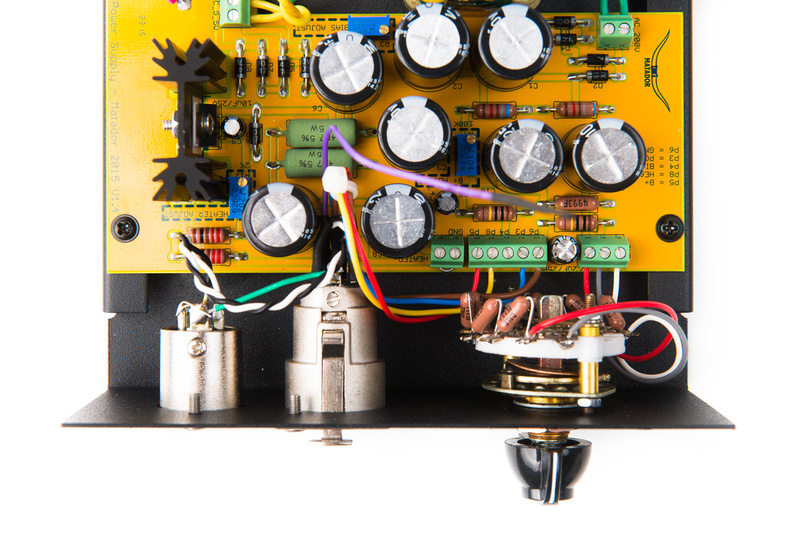
As the passive B+/regulated heater power supply board used in this build is the same as the C12 project and is applicable to other tube microphones, please refer to the following thread for the power supply build. Assemble the PSU in the same manner as the C12 project. We will simply not connect the bias output wire for the ELA M251 build.
https://groupdiy.com/index.php?topic=58054.0
Note, in this specific build, I have opted to re-use the original pattern switch and replace the resistors. There was previously some discussion about the long-term reliability of the sealed Lorlin switch, so I figured I'd offer this "free" alternative as a viable option. I assume the original part is similar to an Alpha type switch.
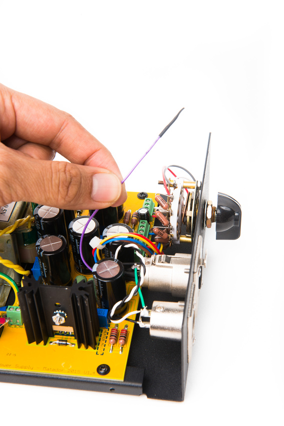
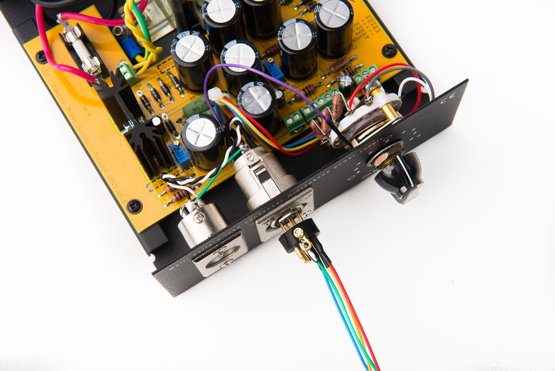
I opted to attach the bias wire to the 7 pin XLR panel jack and cap the wire with a piece of heat shrink tubing and tuck it away inside the power supply. this is not necessary, but allows for the power supply to be very easily re-purposed for a C12 microphone in the future if necessary. Alternately, the bias connection can be fully connected at the power supply and you can simply not connect the wire at the microphone side. In theory, this would allow the power supply to be true dual function between a C12 and ELA M251 if the operating points of both tubes is within acceptable tolerance.
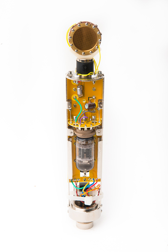
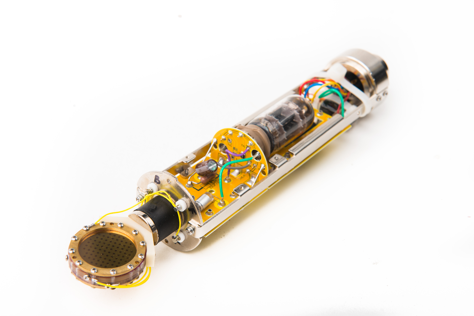
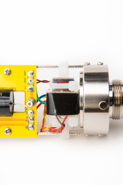
Here is the final wiring setup for this microphone build. Note the loose bias wire (purple) that is not connected to anything as well as the jumper wire between the "GND" and "HEATER - " terminals. The version 1.3 power supply PCB requires this jumper to be installed as the heater ground path is isolated to allow for simple conversion to negative heater supply applications.
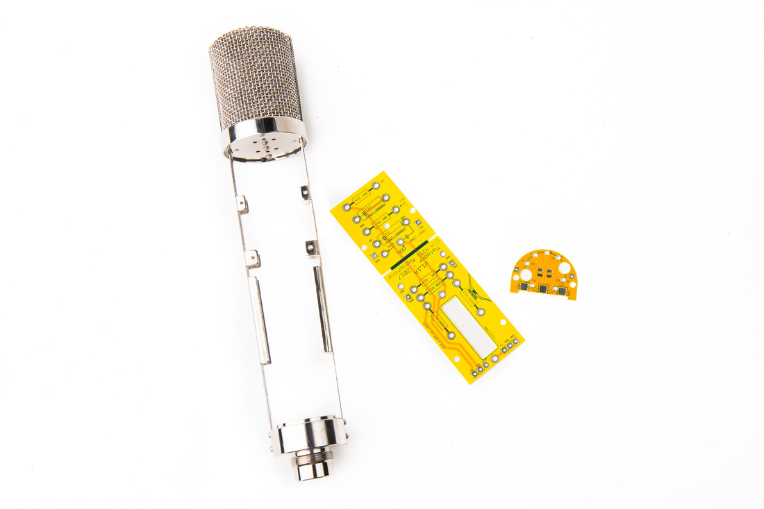
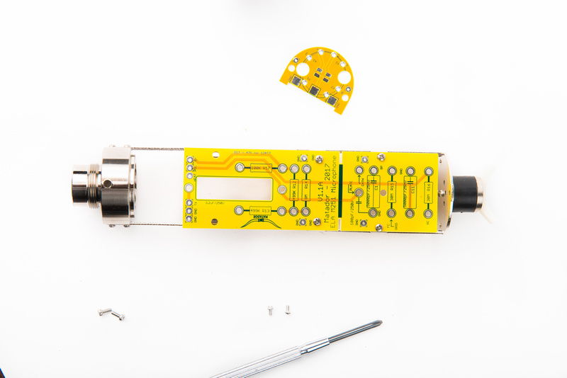
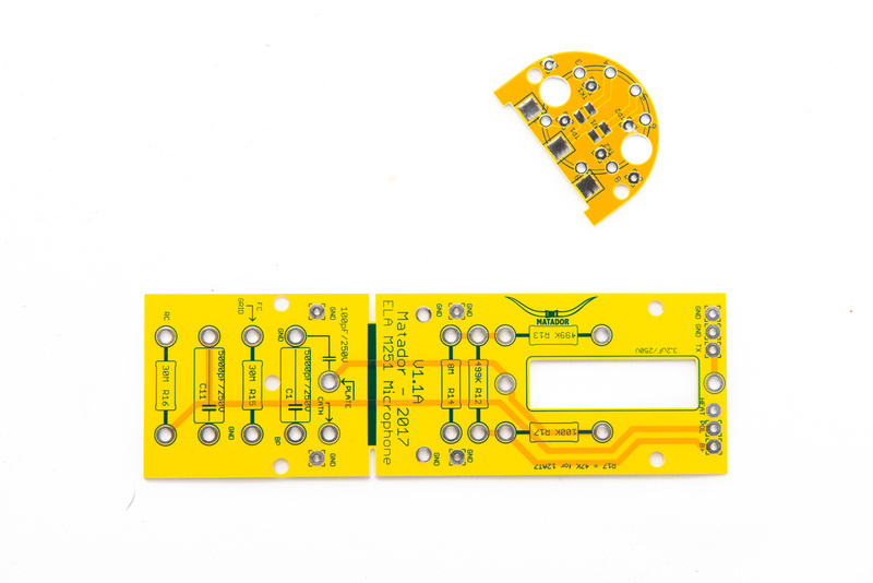
With the power supply complete, I will turn my attention to the microphone body. This board set is designed to fit in an Alctron HT-11A microphone body. I stock a stripped version of this microphone body, and there are many other branded variants of this microphone that can be used like the Apex 460, Nady TCM1150, ShuaiYin SYT1100, Carvin CTM100, etc.
For this build, I will be using an HT-11A body with a Type 3 dual layer headbasket.
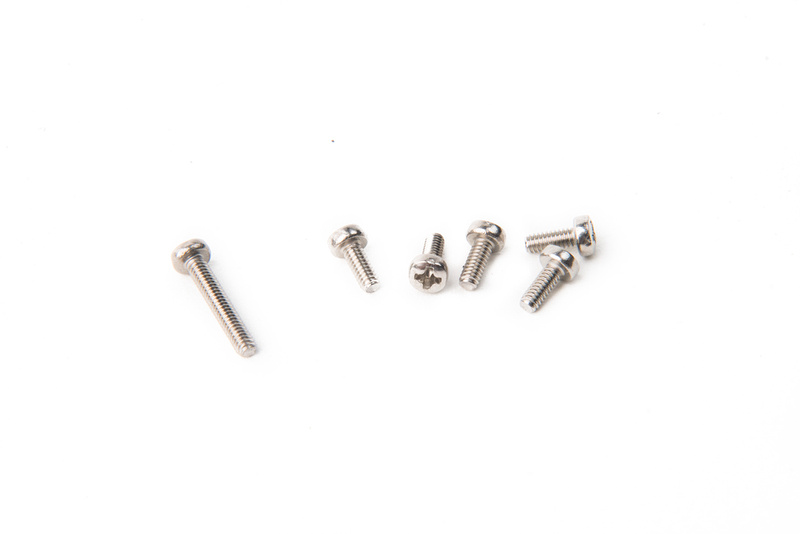
Locate the M2 threaded PCB mounting screws. We will need 5x short ones 4-6mm length and one long one 12mm length.
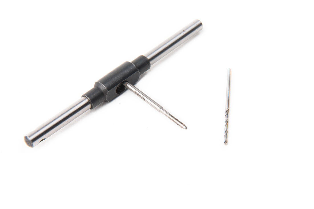
We will also need a 1.6mm diameter or #52 drill bit as well as an M2 tap. Technically, this portion of the build is optional, but I like drill two lower holes into the microphone frame rails to more securely attach the PCB. Both the tap and the bit are somewhat fragile, so if you are purchasing these, it would be advantageous to have a few spares on hand.
Parts tolerances on these imported microphone bodies is not the most consistent so first mount the PCB to the microphone body with the upper 4 screws and check for best alignment.
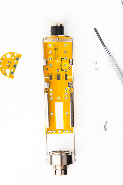
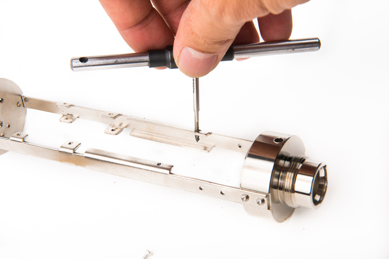
Next, locate the drill locations for the bottom two holes.
I simply use the PCB as a guide and carefully drill through the frame rail being sure to use some oil on the drill bit.
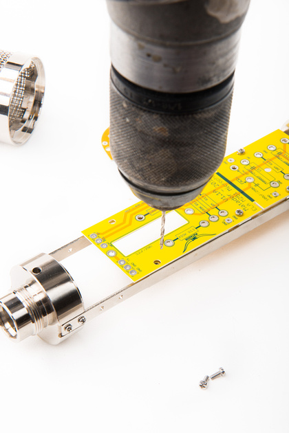
The holes do not need to be perfectly aligned to the PCB holes as there is some wiggle room, but they should be as centered as possible.
Also, be aware of the width of the frame rail. They are somewhat narrow and you may need to favor one side or the other intentionally to center the drilled hole on the available metal surface.
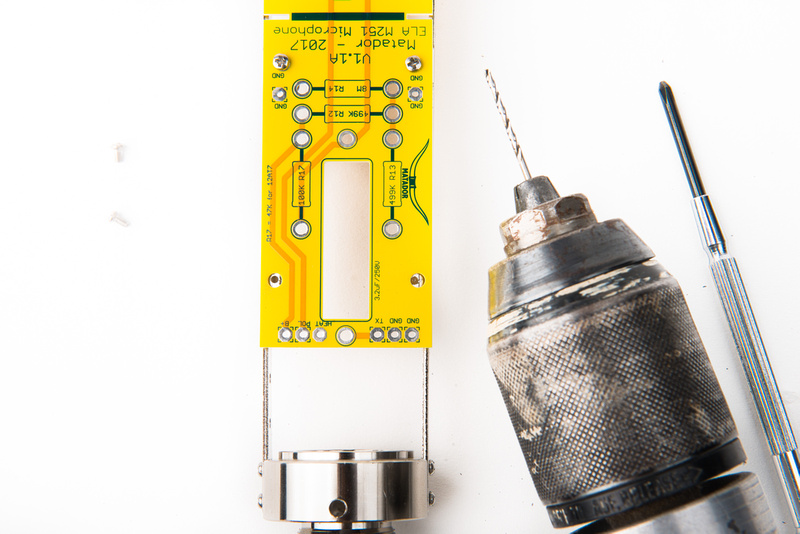
Next, hand tap the drill holes to accept the M2 screws. Again, use some sort of cutting oil on the tap to prevent binding.
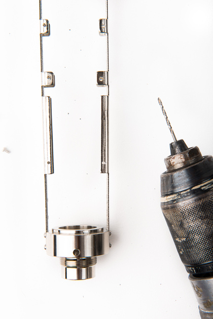
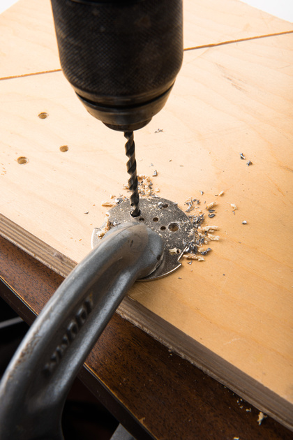
Because this microphone may be used for capsule testing, I am installing teflon turrets to make changing capsules faster. I will drill 3 holes into the top plate to mount the turrets. The hole locations do not need to be super precise, but they do need to avoid contact with the headbasket, the capsule mount, and the frame rails. These turrets are not necessary as wires can connect directly from the capsule to the PCB but I think they make capsule swaps a bit easier.
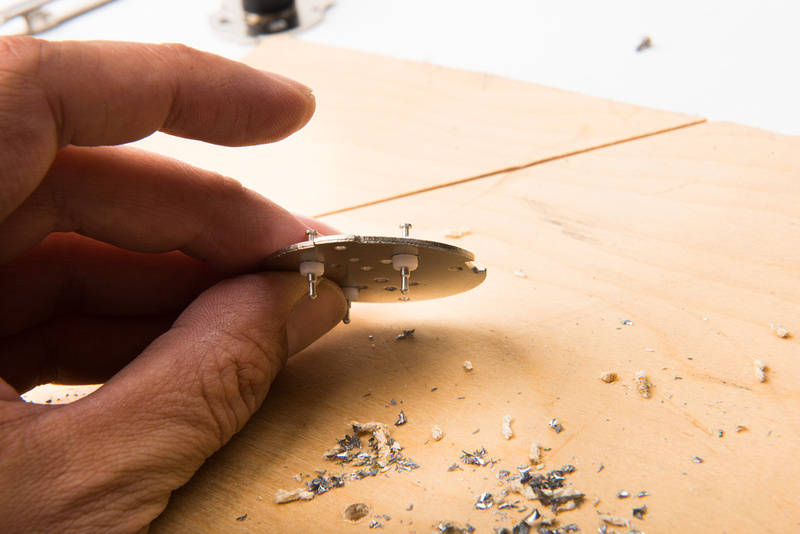
Here, the teflon turrets are in position.
A final test fit confirms that the PCB fits securely into the microphone body with all 6 screws.
One of the teflon turret posts will be very close if not contacting a component turret, so I will need to address that issue when I make my final connections. Most likely I will cut the teflon turret short with wire cutters.
With that, the microphone body preparations are complete and we can populate the PCB.
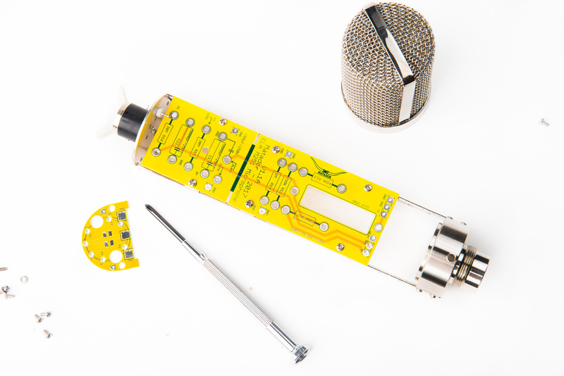
With the microphone body prepared, and the power supply built, we can move forward with populating the microphone PCB set.
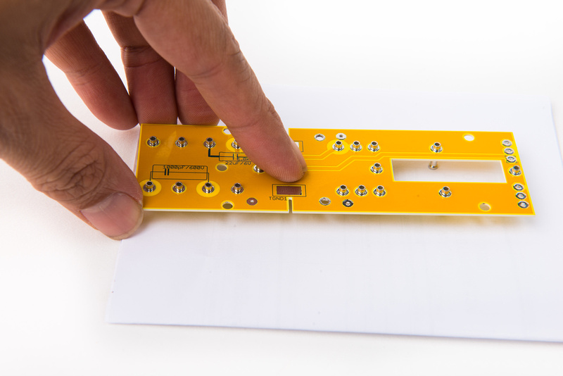
First, locate the Keystone 1540 turrets.
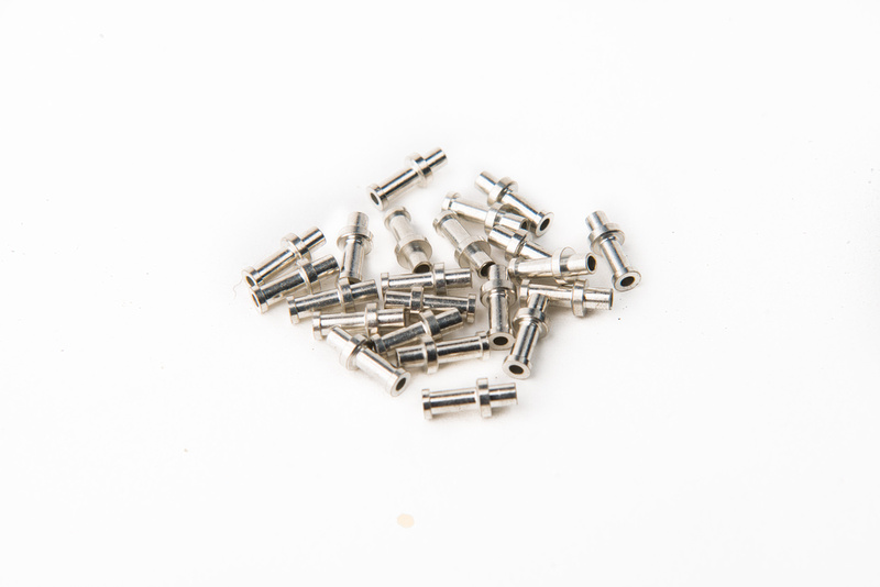
For this build, we will mount all of them to the "front" side of the PCB.
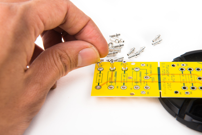
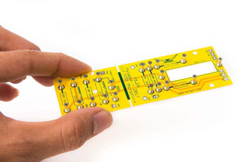
Once all of the turrets are positioned, something relatively stiff and flat to hold the turrets in place while you flip the PCB face down.
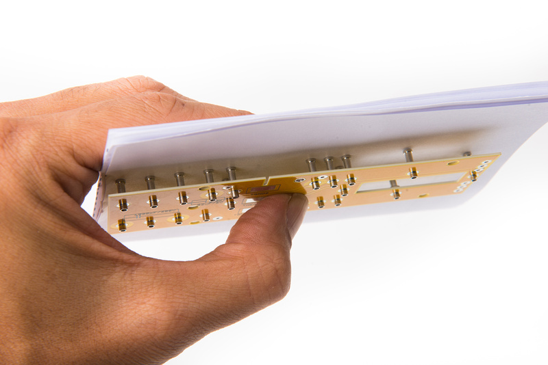
Once the board is flipped over, solder the turrets in place making sure to hold downward pressure on them while the solder solidifies so the turrets are properly seated.
With the turrets installed on the main PCB, let's install the heater power jumper on the tube PCB. A 0 ohm SMD resistor is recommended here because it offers some over-current protection for the tube should you be using an expensive NOS unit, but a simple wire lead jumper can also be used. For this build, we will be using the 2nd leg (pin 5-8) of our 6072A tube. Like the C12, the ELA M251 utilizes only one half of the tube, so we select the one we want to use. In order to save cost, a tube that only tests quiet on one side can be used for the build.
To solder the SMD component with hand soldering tools, first apply solder to one of the pads.

Apply a dab of flux to the pad that you just put solder on.

Next, use tweezers to position the SMD resistor onto the pad and heat the pad with your soldering iron to re-flow the solder that we previously applied and hold the resistor in place from one pad.


With one side secured, the opposite pad can be readily soldered as normal.

Here the SMD resistor is all soldered in.

Next, we will attach the tube PCB to the main PCB. make note of the orientation for the board. make sure it is facing the right.

For optimal alignment, we will solder one of the center pads only to start.

Carefully check for perpendicular placement of the tube PCB before soldering the pad on the opposite side.


Confirm again that the tube PCB is perpendicular before soldering the remaining 4 pads.
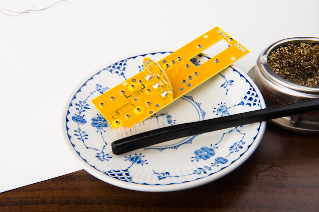
With the turrets and the tube PCB installed, it is a great time to clean the flux residue off of the PCB. Please note, this is NOT an optional step for this microphone project. High impedance sections of the mic circuit are very sensitive to contamination. I recommend using 90% isopropyl alcohol for the job as it works much better than 70%. You will need to use some sort of mechanical means to scrub the board and ensure all of the flux is removed. Change out your alcohol if it becomes saturated with flux and be liberal with it.

Next, we will install the tube socket and jumper wires for Cathode, Plate, and Grid connections to the tube.

The purple wire goes to "TP2" for plate, and the grey wire goes to "TK2" for cathode. If you are using the other half of the tube for your build, you would use "TP1" and TK1" respectively.

After soldering in the cathode and plate jumper wires, clean the connections with 90% isopropyl alcohol.

Because tube sockets can be quite stiff when new, use an expendable "tester" tube and insert it into the tube socket a couple of times before installing it into the PCB. This will put less strain on the assembly when installing your tubes for the first time.

Next position and solder the tube socket into the PCB.


With the tube socket installed, clean the joints thoroughly with 90% isopropyl alcohol.

To strengthen the assembly, locate a thick capacitor lead cut-off and insert it into the PCB assembly.

Solder the reinforcement lead in place and trim the excess.

Do the same for the opposite side.

Next, trim the gray Cathode wire and route it to the turret labelled "CATH". I am connecting to the back side of the turret for cleaner routing. Place the wire, but do not solder it in yet.

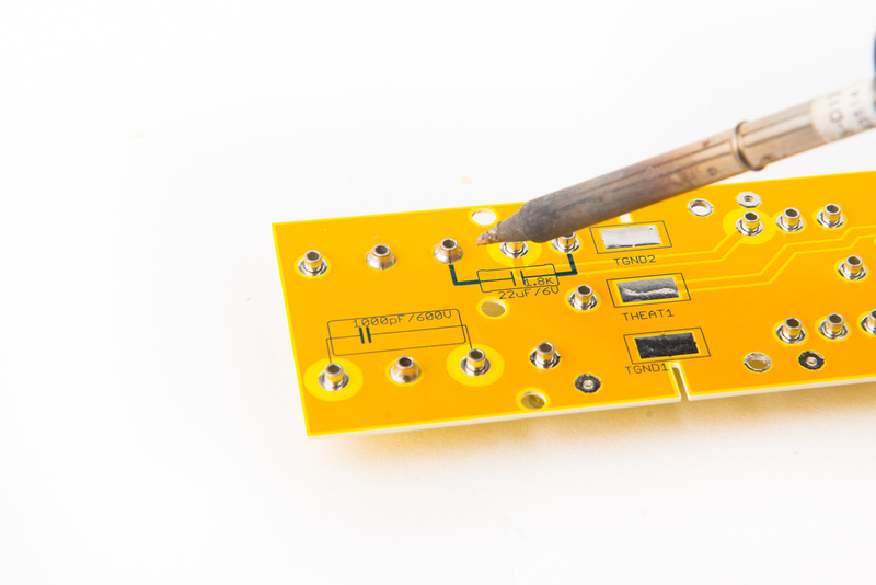
We will be stacking our 1.8K resistor and 22uF electrolytic capacitor in parallel in this location. Note: If you are substituting a 12AT7 in your specific build, use a 33uF capacitor instead.

Position the resistor first and then the capacitor on top of it without soldering. Make sure the polarity of the capacitor is correct with the "-" side going to the grounded lug.

Once positioned, solder these components into place. Next, route the plate wire "TP1 or TP2" to the turret labelled "PLATE". Again, I am routing the wire to the back side of the PCB for clean routing.


Solder this wire into place.

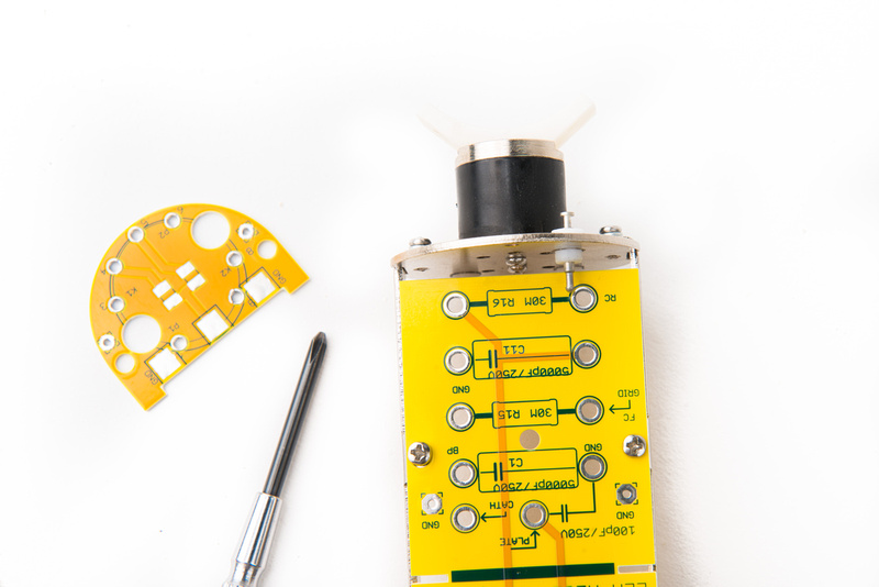
Next, we will begin populating the front side components on the PCB. As I understand it, the standard "correct" way to connect components to turret is by have a 1/2 turn of the component lead around the turret. Begin with the top 30M resistor. Please note, kits contain 10M resistor that substitutes the 8M part indicated on the schematic and PCB. Also, if you are using 12AT7 tube in your build, plase use 47K resistor instead of 100K in the R17 position

After soldering the turret, trim off the excess leads. Try not to put too much heat into the turret as doing so will cause the base solder to melt and the turret will come out of position. If this happens, simply re-heat the effected turret and put it back to the proper position.

Because the turrets isolate the individual components from the PCB surface, I am not cleaning the tops of the turrets with alcohol in this build.

Once the resistors are placed, we can install the capacitors. Note, the polystyrene capacitors are sensitive to alcohol so be careful around them if you need to clean the area.

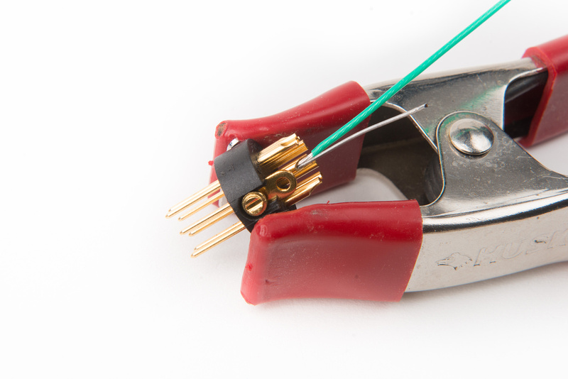
With the front side components installed, let's connect our grid lead directly to the tube socket. I found the easiest way to make this solder connection is to use a small alligator clip to hold the wire to the tube socket lug and solder the connection. Make sure you use the correct side of the tube. Because I am using the 2nd side of the tube, I will use Pin 7.

With the grid wire connected, route the lead to the turret labelled "GRID" again, I am routing to the back side of the PCB. Do not solder this wire yet.

Position the 1000pF capacitor as illustrated below and solder the grid lead and the capacitor into position.


All of the electronic components are now populated on the PCB.


For tube clearance purposes, we will need to trim down one of the turrets. Wire cutters easily accomplish the task.

This allows the tube to sit parallel to the main PCB.

The main microphone PCB is now fully populated. Carefully clean the back side turrets that were soldered on with 90% isopropyl alcohol and Q-tips making sure to avoid the sensitive polystyrene capacitors.
Next, we will prepare the 7 pin XLR insert that goes into the microphone body. Note, the set screw securing this insert works in reverse! To secure it to the microphone body, back the screw out (counter-clockwise) until it pushes outward onto the microphone body. To remove the screw, drive it in (clockwise) to the stop. The insert should wiggle out.
There are many ways to ground a microphone/power supply setup and there is debate about which was is the most proper. I am choosing to connect the ground lead to the microphone chassis at the XLR connector, so the first step is to set the ground wire and run a jumper from that solder lug to the chassis grounding lug on the XLR insert.

Next, we will populate the XLR insert with short wire leads corresponding to the pinouts and wire colors that we selected when building the power supply. In my specific build, I will be using the following:
Pin 1 = B+
Pin 2 = heater
Pin 3 = pattern
Pin 4 = unused (bias in my C12 builds)
Pin 7 = ground
We will leave pins 5 and 6 empty for now as the transformer will connect directly to those.


I like to visually confirm that all of the wires are aligned properly to the PSU wires just to make sure things will not get crossed up during assembly.
With everything confirmed, apply some shrink wrap to the solder lugs.

For this build, we will be using the Cinemag CM-13114 transformer.

The wiring diagram for this transformer as provided by Cinemag shows how to get things set up.

But, mistakes in production have been known to happen, so let's confirm with with a multimeter before putting the transformer into the microphone.
One side of the transformer will have higher resistance than the other. The higher side will go to the PCB, the side with the lower resistance will got to the XLR insert.
Brown and Red measure 1.4K, which is the high side. These two wires will connect to the PCB.

Orange and Yellow measure 29.5R, which is the low side. These two wires will connect to our XLR insert.

Take the orange and yellow wires and thread them through the threaded base piece of the microphone body.

I am designating orange as "audio +" and yellow as "audio -" so we will solder them:
Pin 5 = orange transformer wire
Pin 6 = yellow transformer wire

Push the XLR insert into position and secure the set screw by turning it in reverse (counter clockwise).

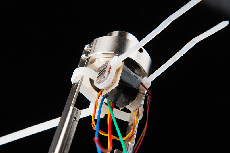
A bell housing is available for the HT-11a microphone body for mounting the transformer, and that can certainly be used, but I prefer to use zip ties and keep everything visible.
We can now attach the fully populated PCB assembly to the microphone body.

To avoid interference, one of the capsule turrets that I previously installed needs to get cut short.

After cutting, I solder in a wire lead to the turret. Again, these turrets are completely optional and not included in the kit. I am setting it this way to facilitate easier capsule swapping for testing on this microphone platform.

Next, locate the M2 screws and secure the PCB to the frame rails.

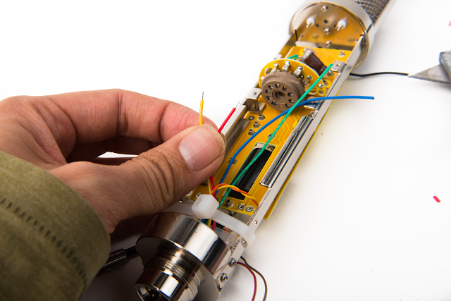
Prepare the wire leads from the XLR insert and route them to the correct solder points on the PCB. It never hurts to double check things here to make sure everything is wired the same as in the power supply.
For my wiring scheme:
B+ = Red wire
POL = Blue wire
HEAT = Yellow wire
GND = Green wire
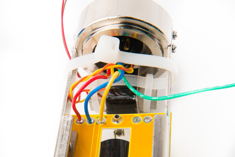
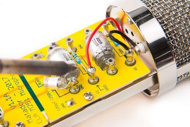
next, locate the brown and red wires from the Cinemag CM-13114 transformer or the two wires with higher resistance from the transformer that you are using in your build. For my wiring scheme,
TX = Brown wire
GND = Red wire

And here is how it looks with the XLR insert all wired up.

Next, we can make the capsule connections at the top of the microphone. I am designating this turret for rear capsule, and the black wire should route to the turret labelled "RC".

I select this turret for front capsule and route the red wire to the turret labelled "FC"
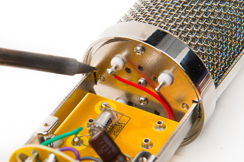
The last turret is for backplate, and I route the corresponding blue wire to the turret labelled "BP"


With everything wired up, we can clean the flux off of the PCB with some 90% isopropyl alcohol and Q tips. Again, be careful around the capacitors.

For this build, I will be using an Eric Heiserman HK12 capsule which is a "proper" chambered capsule. Please note, the Heiserman capsule has isolated backplates that we will need to "tie together" on this build because we retain the polarizing scheme from the C12 microphone. For this build, I will simply run both backplate leads to the same teflon capsule turret.

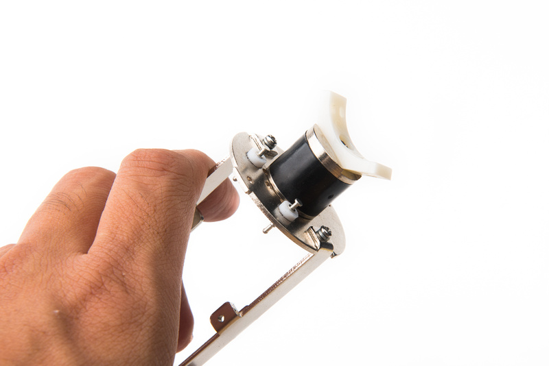
The Heiserman HK12 capsule uses a 45 degree 34mm capsule mount (wide type). I prepare the saddle by clipping off the retaining tabs on the bottom as those are not needed for the rubber base piece on the Alctron mount that comes with the HT-11A microphone body.

Swap in the 34mm wide capsule mount.

And install the microphone to the saddle.

After selecting the screw tabs that I will use for the capsule leads, I install all four lead wires and solder the capsule to the teflon turrets on the microphone body. A ziplock bag protects the capsule from solder splatter.

And here, the capsule is installed.

We can now prepare the microphone cable. I am using Gotham GAC 7 cable which has two thicker 20AWG wires that should be used for the heater and ground connections for this microphone build.

In order to keep everything straight in my head, I make a little pinout chart to keep me on track when I assemble the cable ends.
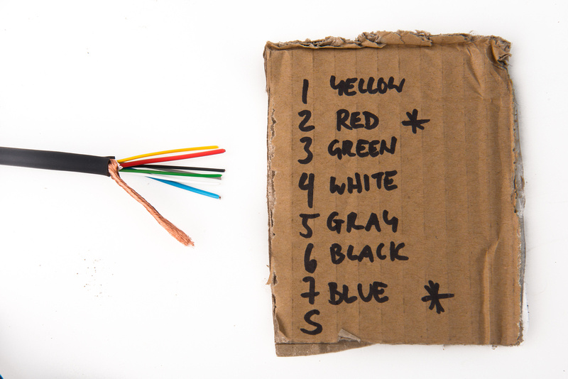
For my build, I will be using:
Pin 1 = Yellow
Pin 2 = Red (20 AWG wire)
Pin 3= Green
Pin 4 = White
Pin 5 = Gray
Pin 6 = Black
Pin 7 = Blue (20 AWG wire)
Obviously, this can be changed to suit your preference. Before soldering, be sure to slide the retainer piece over the cable! Forgetting this step can lead to a lot of headaches.

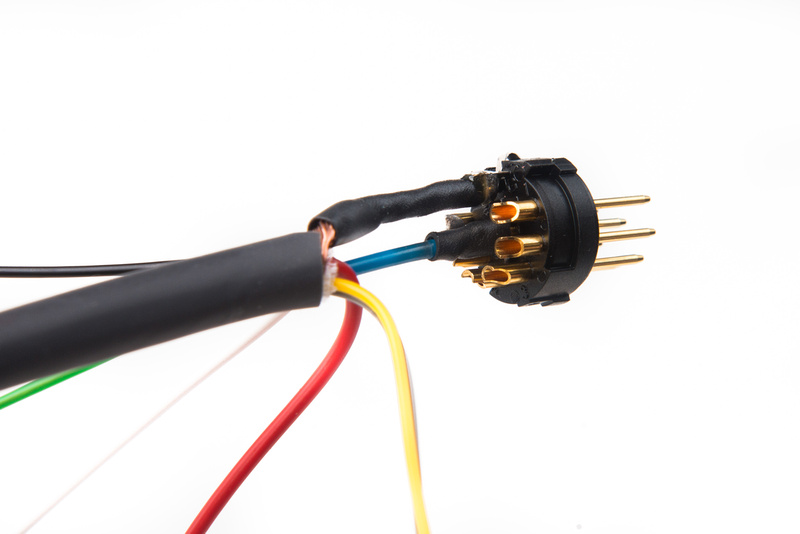
There are many ways to set up the grounding scheme on the power supply, microphone, and cable and some people choose to tie the ground and the shield together. For this build, I am opting to keep the ground wire (pin 7) and the shield separated so I use some shrink wrap and solder the shield to the appropriate tab on the connector. The blue ground wire goes to pin 7. These are the hardest connections to make so I do them first.

Referencing the diagram that I made, I make the rest of the wire connections.

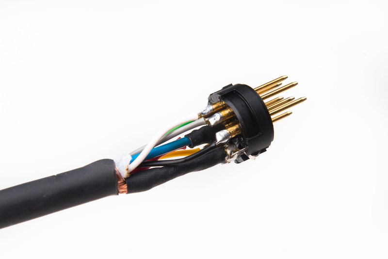
The male end of the cable is similar. Again, the shield and ground connections are the most difficult so I execute these first. Make sure you remember to slide the retainer shell over the cable first before soldering the 2nd side of the cable!
Again, I reference my diagram and make the rest of the connections as cleanly as possible.
With the cable completed, I insert an expendable but known working tube for initial testing. I have an Electro Harmonix 6072A for this job.

And here is the moment of truth. Triple check everything before powering up the microphone for the first time!

No smoke! we are sitting at 117.3V for the B+ which is fine.

And the heater is sitting at 6.28V which is also great.

With no outer casing on the microphone it will be a rumbly, hummy, noisy mess. . . don't worry about that for now. We are simply function testing.
Power down the microphone and remember to wait a sufficient amount of time for the power supply capacitors to fully drain. This may take a few minutes. Once fully powered down, unplug the microphone and install the outer tube. Now, we should have a quiet, clean signal. Check for patterning to make sure that is working properly.

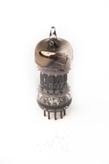
With everything confirmed working, it's time to swap in the final tube. I will be using a 1953 GE6072A 5 star tube supplied by Christian Whitmore. These are selected for noise and microphonics and burned in so they should function flawlessly from the start without drama.
Because this microphone only uses one half of the tube, I save a little bit of money by obtaining a tube that tests quiet on only one side as indicated on the box.

Carefully install the tube!

For the final setup we will want to adjust the heater voltage measured at the microphone as there will be loss over the length of the cable. We start at 6.22V which is fine, but why not get it exact.

A few turns on the trim pot in the PSU, and we dial in 6.3V

The B+ is also adjusted to 119.9V. Because this part of the PSU is passive, the voltage will wander based on the wall power in your specific location. I monitor this for a few minutes and set the PSU to average spot. This voltage should not exceed 120V.

And the microphone is completed. Humans Win!